Login to ProCooling
Name: Pass:
Not Logged In.
Search:
ProCooling Technical Discussions
Overland Storage SnapOS v4 & Image File Links
kiwa 556 Day(s) ago.
/sadmin/debug.cgi
ozmatt 954 Day(s) ago.
Getting back into the water
ben333 1133 Day(s) ago.
ID This Waterblock.
jaydee 1616 Day(s) ago.
ProCooling Geek Bits
Happy 20 year on Procooling!
satanicoo 497 Day(s) ago.
Fluke 17B+ ... the multimeter I've always wanted b...
Noise 1922 Day(s) ago.
Ben's Win 98 box, redone! Build up
ben333 3577 Day(s) ago.
Project Black & Blue - Ben's new HTPC
ben333 3637 Day(s) ago.
Site News and Blogs
User Registrations kinda back open
Jag 1031 Day(s) ago.
New User Registrations are blocked
ben333 1154 Day(s) ago.
Where is Joe these days? JoeKelly.co
ben333 1444 Day(s) ago.
Stuff over the last few years, Blogs, etc...
rhkcommander 1827 Day(s) ago.
The Pro/Market
GTX 280 for US $308.11 !!!!!!
sam amaar 2300 Day(s) ago.
FS: Laptop hardware (CPUs, Memory, HDDs, Wifi, etc...
ben333 4439 Day(s) ago.
FS external watercooling units from jpiperformance...
Halo_Master 4478 Day(s) ago.
FS Snap Server 4200
abuthemagician 4602 Day(s) ago.
Maximizing Maximizing flow rates in H2O setups
Date Posted: Jan 23 2003
Author: pHaestus
Posting Type: Article
Category: H2O and Evap
Page: 1 of 2
Article Rank:No Rank Yet
Must Log In to Rank This Article
Note: This is a legacy article, imported from old code. Due to this some items on the page may not function as expected. Links, Colors, and some images may not be set correctly.
Maximizing flow rates in H2O setups By: pHaestus

Some suggestions for maximizing flow rates in a water cooling setup
By pHaestus                  1/23/03                              Page 1/2


Introduction
My systems have always had T connectors with a fill line in the past.  Not because that is the best way to fill and bleed a system (in fact it isn't especially great at either) but because of space. I never could seem to find the space for a reservoir in my cases because they were either small (PC-50) or crammed full of hardware (all the others). So I stuck with a fill line and a T and waited from a few hours to a few days for the lines to clear of air (if they did).   This has been the weak link in the ease-of-use of all my water cooling setups.

From a technical standpoint, however, the limitation in the final performance of all of my water cooling setups has been the pump. Centrifugal type hobby pumps are just not designed to generate much hydraulic head, and a typical cooling loop is pretty far from their original designed usage. To compensate, I try to make the tubing and routing of the plumbing in my setups as low in flow resistance as possible. Restrictive barb fittings, elbows, t connections, and similar restrictions are not necessary, and are wasting the pump's capabilities without improving cooling.  I figure that this saves the pump's limited pressure for where it is needed: generating water velocity in the waterblock.

Today, I will discuss a method for killing two birds with one stone by using a reservoir that is integrated into the inlet of the centrifugal pump. This makes for a space-saving method to add a reservoir while not restricting the suction side of the pump at all. Before getting into the particulars of the project, however, a bit of background on the rationale and the relevant theory is needed.

Why Care about Pump Intake Restriction?
One of the most serious errors I have seen crop up in other people's cooling loops is the use of a restrictive inlet on the pump.   Take, for example, this 3 valve filling system of pippen88 from the forums :

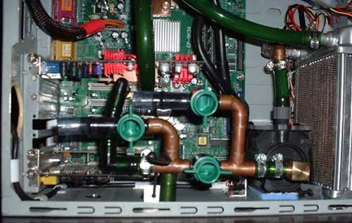
The layman might say "neat piping" or "looks sophisticated", but those familiar with how pumps actually work will say "What have you done to that pump inlet?"  Pumps in general, and centrifugal pumps in particular, should not be throttled on the suction (intake) side.  Ever. I am not trying to single out one person here; I have seen many people using 90 degree barbed fittings on their pump intakes and/or 90 degree fittings throughout their loops.  And just to put those people in good company, also lump everyone that reduces the inlet of their pump with hose barbs in the same category.  Let's look at a bit of theory and explain why this is a bad (awful) idea.

Sources of head loss in cooling loops
I am not an engineer, and my technical training in fluid mechanics is pretty limited.  I rely mostly on a very useful and practical book: Crane Technical Paper 410 "Flow of Fluids through valves, fittings, and pipes" (http://www.cranevalve.com/tech.htm ).  The following equations and numbers are taken from there, and I highly recommend picking up a copy if you find the following discussion interesting.

As a starting point, consider what happens at the molecular level when a pump moves water through a pipe.  The pump exerts work on the water to generate flow, and some of this energy will be wasted by the generation of friction.  This friction may come in the form of water molecules colliding with one another, or it may be friction of water with the walls of pipe. The consequence of these frictional forces is a drop in pressure in the same direction as the fluid flow.  The terms head loss and pressure drop are used interchangeably to describe this loss in pressure across a length of pipe. The Darcy equation defines this mathematically as:

hL = f(L/D)v2/2g

where hL is the velocity head, f is the friction factor (which may be found in tables or determined experimentally), L/D is the ratio of pipe length to internal diameter, v is velocity of flow and g is the acceleration of gravity. This equation is fairly intuitive; for fluid velocity to increase, so to must the head loss. To maintain high water velocity in restrictive pipes, pressure (aka hydraulic head) must be increased.

For fittings and valves, one is no longer simply considering the length of a straight pipe.  Instead, bends and restrictions also affect the head loss.  The above equation now requires a modification:

hL =K v2/2g

where K is the resistance coefficient, which is defined as the number of velocity heads lost due to the valve or fitting.  If desired, one can relate this resistance coefficient to equivalent pipe length by using the Darcy equation:

K = f(L/D)

where f is the friction factor and L and D are the length and diameter of the pipe, in feet.

Since head losses are additive, it is theoretically possible to estimate the total head loss of a cooling loop provided that estimates for friction factors are available for all tubing and fittings and that data exists for the water block and radiator of choice.  For our purposes, however, examining the tabulated K coefficient values in Crane 410 should be sufficient.

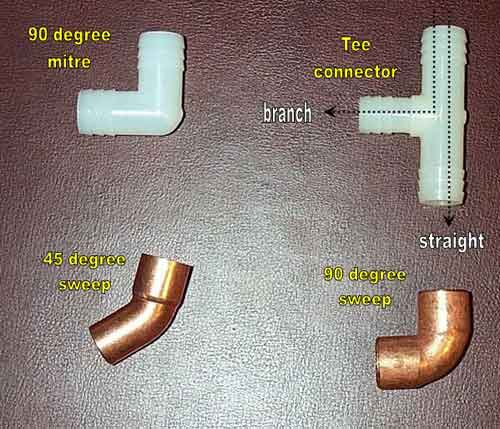
Let's take a look at some commonly used fittings in water cooling loops, a 90 degree mitre connector (aka barbed 90, a 90 degree copper sweep, a 45 degree copper sweep)2 of which make a 90 degree turn, and a T connector.

In this table, f denotes the fully turbulent friction factor.

Fitting

K coefficient

90 degree Mitre

60f

90 degree Sweep

30f

45 degree sweep

10f

T straight through

20f

T through branch

60f

A few quick observations are probably in order.  The absolute most restrictive type of 90 degree turn is the mitre bend used by pippen88 and everyone else who uses the 90 degree brass or plastic barbed fittings. Suggestion: Don't use them.  Somewhat better are copper elbows, but 2 45 degree fittings is a better choice still. The take home message is that any change in flow direction will be accompanied by velocity head loss, and that using mitre bends is the worst solution.  A twofold reduction in head loss accompanies switching from a 90 degree mitre to a copper sweep, and the sweep doesn't require much more space. You will also notice that a T connector produces considerable pressure drop even when flow proceeds straight through the T. Avoiding this will increase water velocity in a cooling loop.

Since I mentioned pippen88's case earlier with regard to the 90 degree mitre fitting on intake and the mess of copper elbows, let's go back and look at revision two of his loop:

Everyone should be able to guess that I like this configuration quite a bit more than the first picture.

More Info and suggestions from the good Dr. this way

Random Forum Pic
Random Forum Pic
From Thread:
Modding Evolution of my beige box
ProCooling Poll:
So why the hell not?
I agree! 67%
What? 17%
Hell NO! 0%
Worst Poll Ever. 17%
Total Votes:18
Please Login to Vote!


(C) ProCooling.com 2005 - All this glorious web geekness was brought to you by Joe's amateur web coding skills.
If we in some way offend you, insult you or your people, screw your mom, beat up your dad, or poop on your porch... we're sorry... we were probably really drunk...
Oh and dont steal our content bitches! Don't give us a reason to pee in your open car window this summer...