|
|
|
|
 Maximizing flow rates in H2O setups Maximizing flow rates in H2O setups
|
|
Date Posted: Jan 23 2003
|
|
Author: pHaestus
|
|
|
|
|
Posting Type: Article
|
|
Category: H2O and Evap
|
|
Page: 2 of 2
|
|
Article Rank:No Rank Yet
Must Log In to Rank This Article
|
|
|
|
|
Note: This is a legacy article, imported from old code. Due to this some items on the page may not function as expected. Links, Colors, and some images may not be set correctly.
|
|
|
Maximizing flow rates in H2O setups By: pHaestus
|
|
|
|
Some suggestions for maximizing flow rates in a water cooling setup
By Derek Peak 1/23/03 Page 2/2
|
|
Pump inlet fittings
What effect does reducing the intake of pump with a smaller fitting have on flow rate? One can similarly calculate the restriction coefficient for a sudden increase in diameter from barb to the larger inlet of pump:
K1 = 0.5(1-b2)
where b is the ratio of small pipe diameter to large pipe diameter and
K = K1/b4
So for a ½" barb adapter on a ¾" inlet fitting, K would be ~ 6 due to the fact that the ID of a ½" barb is very close to 3/8". This presents a substantial restriction to flow and should also be avoided when possible.
Influence of suction line on pump performance
For centrifugal pumps, restriction on the suction (pump intake) side of the loop is problematic even if high flow rates are not of special importance. To properly plumb a centrifugal pump into a system, one should take note of how such pumps are designed. This document: http://www.cepmagazine.org/pdf/050252.pdf is a good starting resource for understanding the factors that affect pump performance. The following discussion is largely taken from that article.
The primary problem with restricting the suction line of a pump is that it increases the potential for cavitation. In a nutshell, cavitation is what occurs when the suction pressure of a fluid drops below its vapor pressure causing vapor bubbles to form in the fluid. Since the density of water vapor is less than that of liquid water, the pump's discharge is decreased. Cavitation can also be damaging to the pump's impeller.
Engineers have a useful term for describing how close that water is to its vapor pressure: Net Positive Suction Head (NPSH). Related terms commonly used are the available NPSH (NPSHA) and the NPSH requirement (NPSHR). The goal is for the NPSHA to be greater than the NPSHR, as means that the total suction head is positive and no cavitation will occur. For water coolers, this can be accomplished in several impractical ways (cooling the water to make it more difficult to reach vapor pressure, increasing the head the pump produces, etc) and one practical way (lowering the NPSHR). Since NPSHR is nothing more than the static head required to reach the desired flow rate, reducing frictional losses of head on the suction line will also lower NPSHR. Increasing the diameter of the suction line and/or reducing the length of the suction line are the usual methods for friction reduction.
The Res/Pump
Given the above information about NPSH and head loss through fittings, I wanted to plumb my current system so that there was as little flow resistance as possible on the suction line. I also decided that I was tired of funnels and T connectors and wanted to add a proper fill point. I played around with a few designs where I added a reservoir to the suction line, but wasn't especially happy with any of them (they didn't really restrict flow any less; they simply added a fill point). On the third try, I hit upon a simple and effective design at last.
|
|
|
|
 |
|
|
|
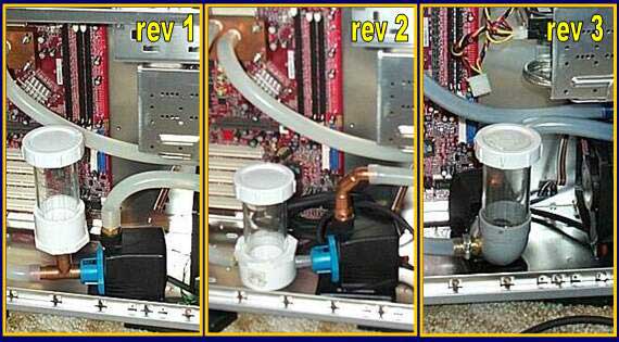
In the first revision, the reservoir was really only there as a fill point and wasn't especially useful at trapping air. In the second revision things improved somewhat, but the inlet of the pump was restricted from the ½" plastic barb I was using to connect the res to the pump. On the third try, I removed the barb altogether and directly attached the res to the pump.
I should note that the res-pump idea is not a new concept; Innovatek makes a mini res that screws onto Eheim pumps , Becooling sells a hybrid pump-res , and overclock-watercool used to do something similar as well. The driving force behind this article was explaining the concepts behind this fill method to those interested in optimizing flow rates in their cooling loops.
Let's take a little closer look at the finished product:
|
|
|
|
|
|
|
|
|
 |
|
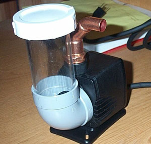
This was a picture prior to Gooping it all in place. The pump is a Hydor L30 (kindly donated by www.cooltechnica.com ), and to properly fit the 90 degree PVC piece it was necessary to cut off the three tabs that hold the stock blue inlet piece in place. I Gooped the pump and impeller housing together and put a lot of pressure on the housing while the adhesive dried to keep everything nice and tight. Then I could simply pop the grey PVC piece onto the pump (and add more Goop of course). To put a cap on my res, I used a hacksaw to cut about ½" thickness of threads off a PVC coupling and then Gooped them onto the top of the acrylic:
|
|
|
|
|
 |
|
|
|
|
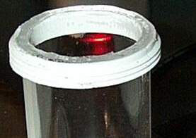
When I first tested the pump-res, I learned something of interest. Since the inlet barb is at a 90 degree angle to the pump's inlet, conditions are perfect for creating a vortex inside the acrylic.
|
|
|
|
|
|
|
|
|
|
This may look cool, but it was sucking air into the pump and causing the tiny bubbles that you can (barely) make out in the discharge line. For testing, I solved the problem by putting a small piece of a plastic pot scrubber into the res. The plastic piece stopped vortex formation even when it wasn't directly in the path of the barb or the pump intake. Pretty ghetto, but it works. I would suggest that anyone thinking about making a res-pump opt for drilling the fitting much higher up on the res so that the vortex doesn't form.
|
|
|
|
|
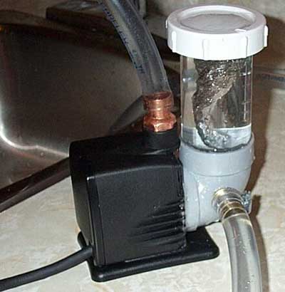
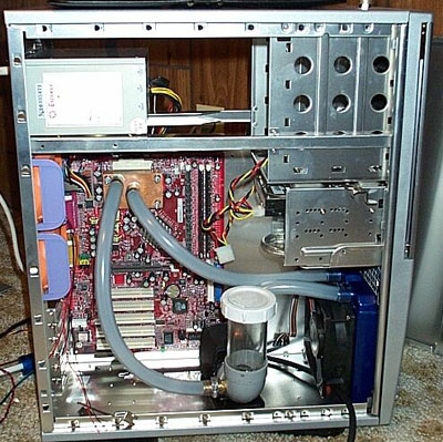
How does it work? Perfectly. The system can be filled in under a minute, and I haven't noticed any air in the lines at all. The pump has all the water it needs on the inlet side, and I have a compact, efficient, low resistance cooling loop:
|
|
|
|
 |
|
|
|
Undoubtedly, your question for me is "Does it cool better after making the changes?" The short answer to that is, of course, "It depends". Flow rates will definitely increase if you remove restrictions in your loop. Pumps will definitely perform more efficiently if NPSHA is greater than NPSHR. Does this definitely mean lower temperatures though? In the end, the pump, radiator, and the waterblock that you choose will largely determine the effectiveness of increasing flow rates. Some waterblocks change markedly in performance from 1GPM to 2GPM flow rates while others do not. For most waterblocks, the difference with my system would be less than 2C. So why bother? In my mind, a low resistance cooling loop is always worth designing. If by lowering flow resistance I can use a smaller pump that generates less heat and noise, then I have still gained even if final temperatures are similar.
Acknowledgements
Thanks to Bruce at www.cooltechnica.com for the Hydor L30, to pippen88 for posting both before and after images of his system on our forums, to Owen Stevens for the copy of Crane 410, to Bill Adams for reviewing a draft of this article, and to the Procooling staff for careful editing.
|
|
|
|
| Random Forum Pic |
 |
| From Thread: Made a Heatercore Shroud |
|
| | ProCooling Poll: |
| So why the hell not? |
|
I agree!
|
 67% 67%
|
|
What?
|
 17% 17%
|
|
Hell NO!
|
 0% 0%
|
|
Worst Poll Ever.
|
 17% 17%
|
Total Votes:18Please Login to Vote!
|
|