|
|
|
|
 The Franken-Opener - iOpener Mod The Franken-Opener - iOpener Mod
|
|
Date Posted: May 1 2000
|
|
Author: Joe
|
|
|
|
|
Posting Type: Article
|
|
Category: Hardware Modding
|
|
Page: 3 of 4
|
|
Article Rank:No Rank Yet
Must Log In to Rank This Article
|
|
|
|
|
Note: This is a legacy article, imported from old code. Due to this some items on the page may not function as expected. Links, Colors, and some images may not be set correctly.
|
|
|
The Franken-Opener - iOpener Mod By: Joe
|
|
Going above and beyond the call of duty to hack this box into a monster
|
|
|
|
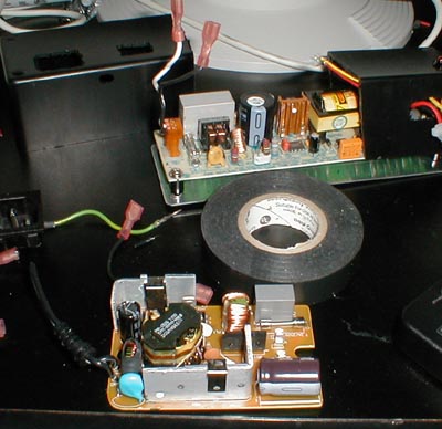
OK so we got this Big ass CPU mounted, and running off your PC's power supply, that's fine and all for a short term solution, I wanted to get a PS that I could mount on the back of the iO and power any and everything 5v I wanted. Then I looked at one of my Liquid cooling rigs and saw I had a perfectly sized PS I ganked from a ext SCSI cdrom case.
|
|
|
|
So I got this lil power supply, and started thinking of ideas on how to power the rig. I really didn't like the idea of having to plug the power brick for the iO in and another power cable for the second CPU. So I had an idea.
Why not run just one power line to a switch that controls both PSU's? SO that's what I did.
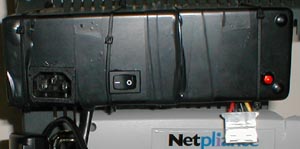
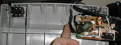
I drove to the local "Shack" and picked up 2 project boxes that I could join together to make one box. So with the help of a dremel tool, a RotoZip (my moms, since I cant do heavy work in my apt, I was using their basement/workbench), I carved the proper holes and mounted the PSU to a metal back plate with some insulating standoffs. I added an LED so I can tell when the PSU is on or not. In the second PSU's box I put in a PC style power plug, and a 120v switch. I ran the plug directly to the switch, and then the switch gave 120v to 2 runs. 1 run went to the second PSU, and the second run ran down to the base to power the now castrated power brick.
|
|
|
|
|
|
 |
|
|
|
|
|
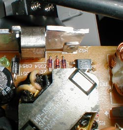
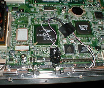
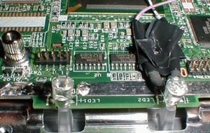
To get the PS to seat all the way down in the cavity made by clearing the ribbing out, I had to bend the HS on a power regulator .
|
|
|
 |
|
|
|
|
|
|
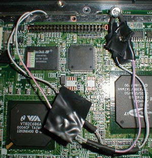
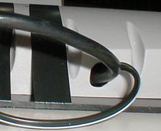
Once I got it all snugly fit in, I secured it with some vinyl electrical tape and then put a piece of lexan type plastic plate over the entire bottom. I haven't bolted it on yet because I haven't found the proper length of screws. so I attached the sheet of plastic with tape for now. The PS does get pretty warm in its new home, but nothing bad. like 90 - 100Deg, if the ambient is 80deg.
|
|
|
|
The second PS was taped around and the different things were secured in place. The PS is Zip tied to the back of the iO, and is solid. That one switch controls both the 19V PS and the 12v / 5v PS for the CPU. It does have a 1 second delay and in some cases wont energize the CPU when the board is brought up and will require you to reboot the machine (hold your finger on the power button for 5 seconds) to get it to Come up.
|
|
|
|
|
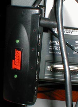
Now getting the 5v Targus ultra small powered USB hub to work
|
|
|
|
With the iO's single USB port it limits you to only one device without using a hub. So if you wanted to use a USB Mouse, you cant use a USB Nic. Since the USB Nic is a key part to this iO, and I wanted to use my extra USB IntelliEye Mouse, I needed to locate a small and powered USB hub.
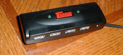
I went to the evil CompUSA and looked around, and found the PERFECT hub! Its a targus 5vdc powered 4 port small USB hub.
|
|
|
|
|
|
|
|
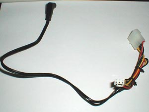
I taped off the 5v run on the second PS. The power wire I use is pictured below. The hub mounts perfectly to the back of the right stand post. its a perfect match. Its has a built in short USB wire so no long wire dangling around. It cost 60$, and was worth it.
|
|
|
 |
|
|
|
|
|
Getting a little Blue Light special action going on
|
|
|
|
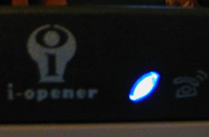
They say its the little things in life that make it all worth it, so I am going after one of those little things. Blue LED's, and an IDE activity indicator are the main things I am going for. Both were easy to do, and were more pretty cool looking after it was done.
|
|
|
|
|
|
 |
|
|
|
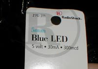
I located some illusive Blue LED's at Radio shack. They cost 3$ per LED compared to .50$ for other LEDs. I placed the 1 Blue LED in place of the left Software controlled green LED, and then removed the right side one and wired the IDE indicator.
|
|
|
|
|
|
|
|
The IDE Activity Indicator-
From what I knew about the IDE setup I knew that if you run a line from Pin 39 to the - side of he LED, and then run a +5v source through a 220Ohm+ resistor to the + side of the LED, and there you have it.
|
|
|
|
 |
|
|
|
There is a pic of the cool blue color that these LEDs make.
|
|
|
|
| Random Forum Pic |
 |
| From Thread: Okay this is it, no really, stop laughing |
|
| | ProCooling Poll: |
| So why the hell not? |
|
I agree!
|
 67% 67%
|
|
What?
|
 17% 17%
|
|
Hell NO!
|
 0% 0%
|
|
Worst Poll Ever.
|
 17% 17%
|
Total Votes:18Please Login to Vote!
|
|