|
|
|
|
 Double Header 2 Double Header 2
|
|
Date Posted: Mar 1 2000
|
|
Author: Joe
|
|
|
|
|
Posting Type: Article
|
|
Category: ProCooling Projects
|
|
Page: 3 of 4
|
Article Rank: from 1 Readers
Must Log In to Rank This Article from 1 Readers
Must Log In to Rank This Article
|
|
|
|
|
Note: This is a legacy article, imported from old code. Due to this some items on the page may not function as expected. Links, Colors, and some images may not be set correctly.
|
|
|
Double Header 2 By: Joe
|
|
Project : Double Header II - Going Cryo
|
|
|
|
Preparing the parts to go to sub freezing temps-
|
|
|
|
|
|
|
|
|
|
 |
|
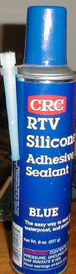
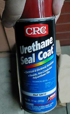
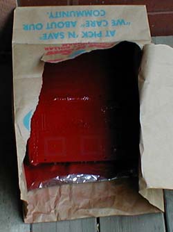
I knew that condensation was going to be my biggest problem once I venture into cold temps. After thinking about it, and listening to N8's personal problems he has had with super cooling on his Bp6, I followed his lead and scored a can or 2 of Urethane Seal Coat made by CRC. It was cheap, like 5$ per can at Gray Bar ((datacom / electrical warehouse). This is a very strong dielectric spray paint used in high voltage applications to seal connections from the elements. It dries to a rubberized coating that is very durable, and can handle temps way more serious then what I will be going for.
|
|
|
|
 |
|
|
|
|
|
Since I cant paint in my apt, and didn't want to coat the deck, I made a makeshift paint booth out of a paper bag. I placed the mobo in the bag upside down and masked some of the areas with duct tape (only stuff I had). I gave the board 3 very careful and controlled coatings. I didn't want to get it on the front of the board. I then gave it a 4th coat that covered the socketed areas more to give it a bit more protection and to make sure the pins are covered with a good thick coat of the sealant.
|
|
|
|
|
|
|
|
|
With the board nicely coated I unmasked the areas that I covered and it all looked good and water proof.
|
|
|
 |
|
|
|
|
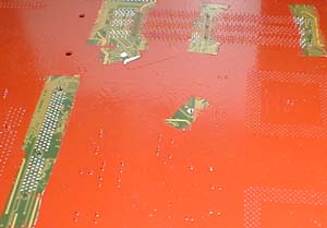
I masked over any areas that the sealant could leak down and into a socket (damaging the socket), or onto the front of the board and covering something that shouldn't be covered. The reason to cover the back of the board is because the cold temps are going to chill the back of the board below the dew point and water will form. this way if it does, the water will form on the urethane and not on the motherboard.
|
|
|
|
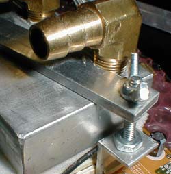
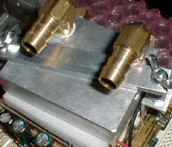
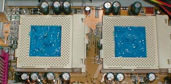
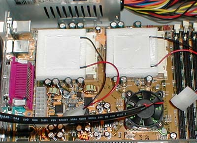
It was time to start sizing up and testing the mounting for the new water blocks / bracket on the pelts. You can also see in the picture the 40mm fan I mounted on the chipset.
|
|
|
|
|
 |
|
|
|
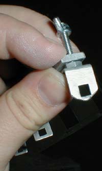
The new bracket has a more professional clip on it that actually didn't fit well on the lug closest to the PS/2 ports, I hit on a device next to the socket so I needed to trim it a bit, then it seemed to fit on just fine. The clips are a bit shorter then the others I was working with and it was a bit tight to get it to hold the blocks on the pelts (not enough screw thread).
|
|
|
|
|
|
|
|
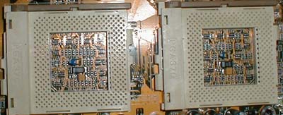
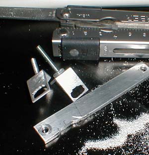
Then disaster strikes
|
|
|
|
Pop Quiz - What's wrong with this picture?
|
|
 |
|
Hint: it really caused some problems with mounting the CPU's....
|
|
|
|
|
|
Yep that's right, "Oh s*it." I snapped off one of the critical end lugs for the mounting bracket. Not good. The reason was because the threads were so close to being shorter then the setup with pelts I tightened it down just to get it to hold on and that was to much for it. For a few hours I was thinking that was the end of the project. But I had enough spare parts for the mounting brackets I was testing for Scott @ Coolchip that I made a modification and mounted it to the big lug that attaches diagonal to the other big lug. It took a lot of hacking and dremel work but It worked great!
|
|
|
 |
|
|
|
|
|
Maybe this will make it easier to see.
|
|
 |
|
|
I took the original clips and the original small brackets (one bracket for each CPU, instead of the one long one). and I made the holes bigger on the clips so they could fit the bigger lugs, and also by hand and with a file (didn't have my dremel around when I needed it) I filed a area out of the bracket to fit around the fitting on the water block that is on the top because it is running diagonal across the CPU.
|
|
|
|
Once that fubar was out of the way, I was able to get on with the remainder of the sealing. It was time to bust out the RTV and seal anything that was left unsealed by the urethane. Mainly the top of the mobo, and components going into the cooling setup.
|
|
|
|
|
|
|
|
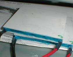
This was a poor attempt at potting the pelt but it gets the job done. I bought some real 3M potting compound and I will use it in my next rig (1.8oz of it cost 15$!!!) (notice the green C, for Cold, its always helpfull!)
|
|
|
I also filled in underneath the CPUs. Not enough to touch the CPU's, but enough to fill the cavity. I bent the thermal probes straight up before this and then once I had the goop in the area, I would set the CPU down and lock it in so that the thermal probe would always be at the correct height.
|
|
|
|
|
|
|
To fill up the rest of the area between the CPU and the silicone, I filled it with thermal paste, as an air displacement goop.
|
|
|
|
|
|
|
| Random Forum Pic |
 |
| From Thread: Please judge this design! |
|
| | ProCooling Poll: |
| So why the hell not? |
|
I agree!
|
 67% 67%
|
|
What?
|
 17% 17%
|
|
Hell NO!
|
 0% 0%
|
|
Worst Poll Ever.
|
 17% 17%
|
Total Votes:18Please Login to Vote!
|
|