|
|
|
|
 Sharing the Load between PSU's in a system Sharing the Load between PSU's in a system
|
|
Date Posted: May 1 2003
|
|
Author: Yo-Duh_87
|
|
|
|
|
Posting Type: Article
|
|
Category: Electronics
|
|
Page: 2 of 2
|
|
Article Rank:No Rank Yet
Must Log In to Rank This Article
|
|
|
|
|
Note: This is a legacy article, imported from old code. Due to this some items on the page may not function as expected. Links, Colors, and some images may not be set correctly.
|
|
|
Sharing the Load between PSU's in a system By: Yo-Duh_87
|
|
|
|
|
Sharing a load between multiple PSUs
By: Yo-Duh_87 5/1/03
( was really wrote months earlier )
|
|
|
I sent this article to bigben2k while it was being looked over by the ProCooling staff to get another opinion on things. One of his questions was: Do the supplies share the load equally?
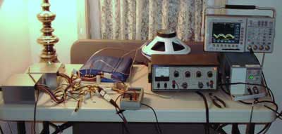
So, doing a little investigating, I asked my dad to bring home a current probe and oscilloscope so I could answer correctly. When I got the results, I noticed something funny; one supply was taking more load than the other. Also, the supply that was bearing most of the load had the higher voltage of the two.
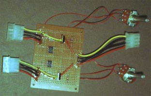
I also took a picture of my test setup, for your amusement :D
|
|
|
 |
|
|
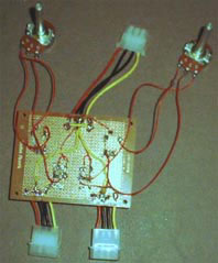
Now, my goal was to perfect the sharing of the supplies, just to prove the theory. I used 2 potentiometers (pots), one for each supply, between the FET driver and the mosfet, regulating the voltages of the supplies voltages so that they matched.
|
|
 |
|
|
|
I don't recommend using this method if you were to build this circuit, instead use the pots commonly found inside computer PSUs to make the adjustment. This was only done so that I could tweak the supplies as close as possible via minute adjustments to the 2 pots. Using mosfets as linear regulators is generally not a good idea, as it causes the mosfets to dissipate current, which may make them grow very hot. I personally only have a .3v difference, and by touching the mosfets, you wouldn't know the difference.
|
|
|
|
|
|
|
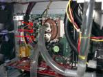
|
Below is a picture of the final build:
|
|
|
|
 |
|
|
|
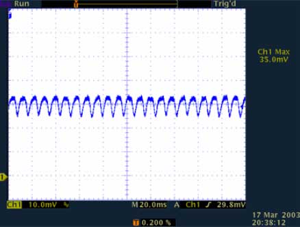
This first picture is an oscilloscope reading from the first PSU, according to the reading, the PSU is supplying 3.5A.
|
|
|
 |
|
|
|
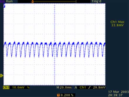
This picture is of the second PSU, and while the waveform looks different than the first PSU, it is supplying 3.38A.
|
|
 |
|
|
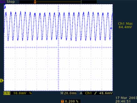
And this last image is a reading of the current output of the circuit, about 6.44A total being pulled from both PSUs.
|
|
 |
|
|
I have to say that it was a smashing success. Using the same car amp I used in the previous tests, I had a near perfect (within .12A) 50/50 share. Even when adjusting the load to use more/less current, the sharing didn't make dramatic changes. The pots were very touchy and even bumping the table could alter the load sharing.
If you were to make this adjustment in a normal supply, you will need an ohmmeter and a large load for calibration purposes. All you need to do is adjust until the VGS voltages on both mosfets are equal.
|
|
This method worked well for me, and was well within the minimum requirements as far as the testing went.
I have since decided to not use the PC power supplies, though, for several reasons: I would have needed at least one more to provide the required power, they are bulky, and they are wasteful (I don't need all those 5v, 3.3v, etc lines!). I have since decided to build my own power supply, as I have now found a source of cheap transformers ;)
|
|
I wonder what would happen if I used two of these??
|
|
If you have any comments or Questions please email me at crjunk@whitesidefamily.net
|
|
|
|
| Random Forum Pic |
 |
| From Thread: hotspot now that im watercooled |
|
| | ProCooling Poll: |
| So why the hell not? |
|
I agree!
|
 67% 67%
|
|
What?
|
 17% 17%
|
|
Hell NO!
|
 0% 0%
|
|
Worst Poll Ever.
|
 17% 17%
|
Total Votes:18Please Login to Vote!
|
|