|
|
|
|
 pH's guide to wiring up pumps in your H2O rig pH's guide to wiring up pumps in your H2O rig
|
|
Date Posted: May 3 2002
|
|
Author: pHaestus
|
|
|
|
|
Posting Type: Article
|
|
Category: Electronics
|
|
Page: 2 of 2
|
|
Article Rank:No Rank Yet
Must Log In to Rank This Article
|
|
|
|
|
Note: This is a legacy article, imported from old code. Due to this some items on the page may not function as expected. Links, Colors, and some images may not be set correctly.
|
|
|
pH's guide to wiring up pumps in your H2O rig By: pHaestus
|
|
pH's Guide to Wiring Pumps
|
|
|
Let's get Fancy - Using a relay
|
|
Relays are quite useful pieces of electronics for many applications. A relay is basically a switch that is activated electronically by voltage being applied to an electromagnet that moves the switch, rather than by mechanically flipping a switch. It is possible to choose a relay that can be used to automatically turn your pump on whenever you press the power button of your computer.
I am going to digress for a moment and point out that I personally do not use or recommend using relays. Most pumps that are used in water cooling setups are designed for continuous usage, and every time that they are turned off and on some damage to the pump occurs and the life expectancy is shortened. Since my Eheims and Danners have all been basically silent anyway and do not draw a huge amount of power I just do not see a good reason to knowingly damage them. Furthermore, adding more complexity to the system is always going to increase the chance of failure. I just run my pumps all the time.
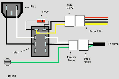
If you aren't dissuaded by my comments and still want to use a relay, then you should choose a relay that is activated by either 12VDC or 5V DC (12V ones are far more common) and that can handle the amperage of your 110VAC pump (usually not a problem). There are two major kinds of relays: NC (Normally Closed) with the contact closed by default, and NO (Normally Open) with the contact open by default. For our purposes, NO type relays are appropriate (when voltage is applied, the circuit is completed and power goes from input to pump). A typical relay wiring setup is shown below:
|
|
 |
|
|
|
There are a couple items to note from the diagram. First of all, it is possible to connect the relay to either the PSU or the extra socket that was wired up earlier without problem. Next, the ground and live wires should not both be connected to the relay. Only the live wires are needed. Another important thing to note is the diode in the diagram. It is set up so that when power is turned off and the electromagnetic coil collapses that there is no power surge to your PSU. This can be quite dangerous to your components, but it can cheaply be solved with a reverse biased (connected "backwards") diode to prevent the burst of current from flowing back into the PSU.
By the way, if this looks like a bit more than you want to take on yourself, then this professionally made setup is available.
|
|
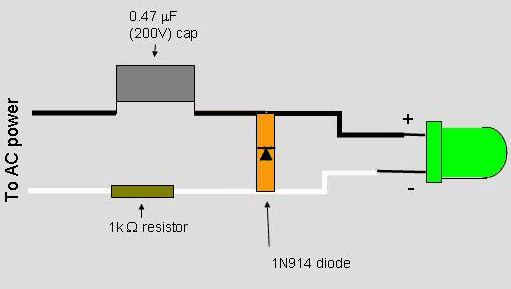
One project that many people are interested in doing is adding an LED that lights up whenever the pump is running. You may find it contradictory that I talk about relays as being unnecessarily complicated up above, and then go through the trouble of wiring in an LED indicator for my computer. Well first off, shiny things always impress me; and second, the addition of an LED isn't going to cause your pump to fail any sooner. The circuit is nothing more than an AC to DC converter, with the capacitor and resistor chosen to produce a voltage and current appropriate for the LED. Here is the diagram:
|
|
 |
|
Simply solder the AC input to either the relay or the switch so that it only gets power when the pump is switched on. I have to give credit where it is due. I first saw this LED indicator in a forum post by Turbokeu (the guy from Belgium with the truly amazing PC-70), and then tracked down a schematic online. The second link has a nice explanation of how the capacitors and resistors were chosen, and so I am going to just quote it here:
"The resistor value (1K / half watt) was chosen to limit the worst case inrush current to about 150 mA which will drop to less than 30 mA in a millisecond as the capacitor charges. This appears be a safe value, I have switched the circuit on and off many times without damage to the LED. The 0.47 uF capacitor has a reactance of 5600 ohms at 60 cycles so the LED current is about 20 mA half wave, or 10 mA average. A larger capacitor will increase the current and a smaller one will reduce it. The capacitor must be a non-polarized type with a voltage rating of 200 volts or more"
|
|
There are advantages and disadvantages to all of the methods of pump wiring I have discussed here. If you never plan on swapping out your PSU and don't care about its warranty then soldering the pump's power wires to the switch in the PSU is the simplest and cleanest method to use. If you are concerned about opening up the PSU or you change them regularly then adding a second socket for the pump's power is a better solution for you. I don't recommend relays for magdrive-type pumps at all; the pumps are designed for continuous usage. If there is something that is in error or is missing from this article please contact me and I will try to address it.
|
|
If you have any comments or Questions please email me at pHaestus@ProCooling.com
|
|
|
|
| Random Forum Pic |
 |
| From Thread: New Swiftech MCX-159 chipset heatsink |
|
| | ProCooling Poll: |
| So why the hell not? |
|
I agree!
|
 67% 67%
|
|
What?
|
 17% 17%
|
|
Hell NO!
|
 0% 0%
|
|
Worst Poll Ever.
|
 17% 17%
|
Total Votes:18Please Login to Vote!
|
|


 pH's guide to wiring up pumps in your H2O rig

