|
|
|
|
 Aardils PWM Fan Controller Review Aardils PWM Fan Controller Review
|
|
Date Posted: May 6 2003
|
|
Author: Brians256
|
|
|
|
|
Posting Type: Review
|
|
Category: Thermal Management Reviews
|
|
Page: 2 of 3
|
|
Article Rank:No Rank Yet
Must Log In to Rank This Article
|
|
|
|
|
Note: This is a legacy article, imported from old code. Due to this some items on the page may not function as expected. Links, Colors, and some images may not be set correctly.
|
|
|
Aardils PWM Fan Controller Review By: Brians256
|
|
|
|
|
|
Preview: Aardil's PWM Fan Controller
|
|
|
|
Both controllers came shipped in an anti-static bag, well cushioned by the standard packing peanuts.
Aardil knows how to ship something with low cost but good protection. As for documentation, the first prototype had only a single sheet. But, before you judge too harshly, Aardil sent me an improved version as a Microsoft Word™ document even before I got a chance to test. I can also report that, the latest revision came with several sheets of documentation (far more than you really need). You can definitely know that he is interested in making the fan controller better, because documentation really is the least fun part of manufacturing a new product.
The circuit boards are different from a large manufacturer, because they use through-hole components (the chip pins go through the PCB) instead of SMT (surface
mount) components. The first prototype had pits in the copper traces, but that was cleaned up in the final revision. For cost reasons, though, Aardil still uses through-hole components.
Does it matter? No.
Through-hole components are much easier to assemble for low-production volumes, and they tend to be the heavier-duty as compared to their pint-sized SMT cousins. Bigger is usually better when you are dealing with power. Plus, you have a better chance of modifying a board like this than those tiny SMT chipped boards. Have you ever tried soldering onto a SMT chip? pHaestus has some good pictures of how hard it is to solder onto SMT chips in this thermal diode article.
As for the pitted copper traces, that is an artifact of the manufacturing process used for the prototype. The second prototype is beautiful in comparison.
Basically, the first PCB was prototyped with laser printer etch patterns ironed onto a copper clad board. With this prototype, his laser printer was low on toner and didn't fill in the black areas as evenly as was needed to keep the etchant solution from pitting the copper traces. Does it impair performance? No. The copper traces are already oversized enough to deal with far more electrical energy than the components can withstand. The second prototype is not as beefy in trace width, but the traces are covered with conductive tin, thus adding extra conductor for all that current flowing to your 235CFM fans.
|
|
|
|
|
|
Easy to Use?
|
|
|
When I got it, I needed to create two power cables, which was a pain. But, that isn't entirely Aardil's fault. One cable was needed
because the power connector is the style seen on floppy drives.
I needed another adapter cable because my fans are driven off of 4-pin molex connectors that you see on hard drives. Aardil's controller supplies power with a 3-pin header that is used to power CPU fans and such.
My test bench PSU is from an old external hard drive case, so it didn't have any floppy connectors. After quick snips, wire stripping and some soldering,
I had a conversion cable. No big deal, but I know Aardil could ship with one for a small extra charge.
He estimated cables (connection conversion and splitter) at about $3, but also he also stated that they should also be available at local computer stores.
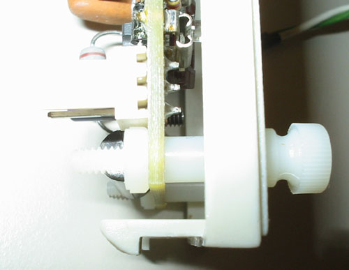
The pots (adjustable resistance potentiometers) on the front are not as easy to adjust as a big knob, but that is actually a good thing.
I have three kids who love to play with knobs and buttons. For some reason, blinking lights on my computer don't help the situation. So, for me, I set the desired temperature and it never gets changed by inquisitive fingers.
To adjust the fan controller, you place the thermistor onto a surface that needs temperature control. For me that is the heater core in my H2O loop.
For someone else, it could be the CPU heatsink, a northbridge heatsink or something in the power supply. Basically, you want to attach the thermistor to something that will get cooler when the fans turn on and get hotter if the fans don't turn on.
There is probably a better way to affix a thermistor, but I simply used hot glue. I used some arctic silver to make good thermal contact between the
thermistor and the heater core, and then put a big blob of hot glue over the entire mess. Important note: hot glue does not stick to arctic silver!
If you use thermal grease, be sure to only get it between the thermistor and the object being watched. I smeared it all over, trying to get the thermistor positioned just right, and then the hot glue wouldn't stick to the heater core.
After positioning the temperature sensor, you need to adjust the fan controller to be on when it needs to be on and off when your system is cool.
To do that, I got my system going and then turned the fan control faster (counter clockwise!) until the CPU temperature was acceptable. This means that the fans won't be on when the system first powers up. As the water heats up, the temperature will hit that threshold temperature, and Aardil's controller turns the fans on to limit the heat.
There are several other controls on the front panel, including one control that may be removed. One is the ramp speed. That means that when the
temperature gets to the threshold, the fans may turn on gradually or suddenly.
Another control is the LED set point. When you get the temperature threshold tuned, you need to adjust the LED so that it is on when the fan is on and off when the fan is off. This one seemed unnecessary, but I believe it saved Aardil from adding more components to the PCB. Oh well, I never changed it once I got it set.
Installation of the PCB itself was extremely easy.
As you can see from the first picture, the PCB is actually mounted behind a plastic drive bay cover. Note that the plastic bay cover is not included. You provide your own and drill holes according to a supplied template. Aardil has been unable to find a supplier for limited quantities of these covers. If you have a good supplier, let him know.
|
|
|
|
|
|
|
|
|
|
|
|
|
 |
|
|
|
|
|
|
More Power Scotty!
|
|
This was already covered in some details before, but basically a fan controller must be able to handle the fans you want to attach, and then it must be able to
fail gracefully if you mess up.
For my first test, I used several CPU fans and PSU fans for individual tests. The first prototype failed on all but a small 40mm fan. They wouldn't
start! You could get some of the running if you used your finger to get them going and then the PWM controller would keep them running at a slow speed. However, that's not what I was hoping for.
The second prototype ran all types of fans successfully.
For a second test, I installed five 120mm fans (Nidec Beta-SL fans using 0.86 amps at 12VDC) for a total of 4.3 amps of load. Just under the five amp
maximum, to be sure that I didn't blow the fuse. The first prototype obviously could not run them, but the second prototype ran them in style! Smooth and quiet.
I mentioned smooth and quiet specifically because my own PWM fan controller is not smooth.
It stutters, for want of a better term. I believe that Aardil added a capacitor to help smooth the normally staccato PWM output. This helps not turn the fan on and off quite so sharply and you don't get sudden jerks in applied power.
|
|
|
 |
|
|
|
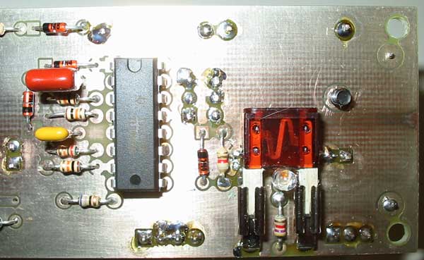
See the fuse? This is what helps prevent forest fires, kiddies.
If you attach too many beefy fans to the controller, the fuse will pop right away instead of lasting for 6 hours. That way, the board won't decide to fail when you are asleep and let your cherry-picked CPU turn into an expensive and ineffective paperweight. It is better to have a fuse fail when you are first testing than to fail when you are away or otherwise not paying attention! Fuses only cost a dollar or two.
As for beefy power capacity, take a gander at this baby.
|
|
|
 |
|
|
|
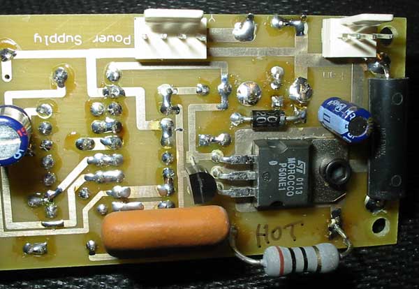
See the word "HOT" and the black chip above it? That big black chip with three legs pointing to the left is the power MOSFET, and it handles all the
current going to the fans. Well, don't be fooled by the word "HOT".
The power MOSFET doesn't get hot at all. The only hot component is the light purple resistor just below the MOSFET, and it doesn't even get that hot. The ST MOSFET was chosen so that it could handle a full five amps of current without breaking a sweat.
What about the PCB traces?
It turns out that the PCB design is beefy as well. The design specifies one ounce copper on FR4 PCB material, double sided with plated throughs, and immersion silver plated with soldermask. What we are interested in is the trace width and thickness, as these tell us how much amperage can safely run to the fans. By looking at this site on Copper Foil thickness, we see that one ounce copper means that the copper is the same thickness as if one ounce of copper was spread across a square foot of PCB. Along with the width (about one eighth inch width, which is 0.125"), we can look at this article on current carrying capacity and see that the traces can carry over 4 amps and still stay at 10°C above ambient temperature. An FR4 (flammability rating 4 which is the second best) board can easily handle even 20°C rise without danger of trace delamination (where the traces separate from the board) or any fire hazard.
|
|
|
|
Performance, Cost and Conclusion
 |
|
|
|
|
| Random Forum Pic |
 |
| From Thread: Site is over 16 years old... |
|
| | ProCooling Poll: |
| So why the hell not? |
|
I agree!
|
 67% 67%
|
|
What?
|
 17% 17%
|
|
Hell NO!
|
 0% 0%
|
|
Worst Poll Ever.
|
 17% 17%
|
Total Votes:18Please Login to Vote!
|
|


