|
|
|
|
 How to link multiple AT PSU's into one BIG PSU. How to link multiple AT PSU's into one BIG PSU.
|
|
Date Posted: Apr 1 2001
|
|
Author: OnDaEdg
|
|
|
|
|
Posting Type: Article
|
|
Category: Electronics
|
|
Page: 2 of 2
|
|
Article Rank:No Rank Yet
Must Log In to Rank This Article
|
|
|
|
|
Note: This is a legacy article, imported from old code. Due to this some items on the page may not function as expected. Links, Colors, and some images may not be set correctly.
|
|
|
How to link multiple AT PSU's into one BIG PSU. By: OnDaEdg
|
|
|
|
|
|
|
|
|
|
How to Run 2, 4, or even 10 (AT) Power Supplies In Parallel or Series at 5, 12, 18, or 24 Volts!
|
|
|
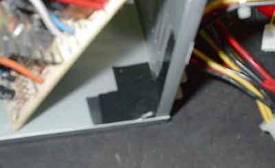
Now that I have found where the negative is touching the case, I did one last visual check for any other place where it may be connected to ground. So I checked underneath of all four mounting holes as well as taking ohm readings from various points to the case. This appears to be the only place where the negative side is connected to the case. With the circuitboard lifted off the case, I did one last test and it was negative. Ok, now we know where they're touching. What are we going to do about it? There are several options. I am going to list them from best to good in that order.
1. Taking an Xacto knife, remove the copper clad around each mounting hole by making a 1/2 inch circular cut around it. Or, you can use a rotary tool and a small grinding bit to remove the copper clad from being in contact with the rest of the circuit board.
2. You can use nylon washers to and bottom. They come in sets for different size screws and have a slight collar to keep the mounting screws from slipping sideways. (I would try to use nylon screws as well. The metal bolts scare me)
3. Use plastic standoffs used to hold the motherboard off of the case. Many of you have these.
Due to the design of this particular power supply, there was almost no room for me to grind away or cut the copper clad. Instead, I chose to do a massive insulation job using good quality electrical tape.
I cut up about 6 strips of electrical tape and covered the mounting hole for at least an inch in any direction around it.
|
|
|
|
 |
|
|
|
Furthermore, I tested the circuit board using just three of the four screws to hold it to the case and it was still very sturdy so I did not use the screw that held the circuit board down in that corner. This should pose no danger of any kind since the power supplies will be sitting straight up anyways. Now that it is completely insulated from the circuit board, I rebooted the circuit board down and it's time to run the ohm and continuity tests again. I again touched one probe to the negative(black wires) and the other to the case:
|
|
|
|
 |
|
|
|
The tests were negative! There was no beep nor did my ohm meter measure little or no resistance. In other words, the negative is no longer connected to the case. Let's put the cover back on and see what we can do with two power supplies connected in series or parallel.
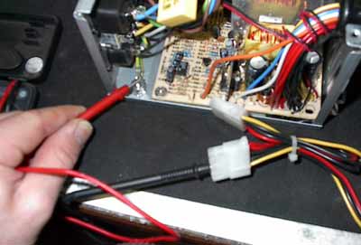
First off, we must connect the 1 or 2 ohm resistors I mentioned in the supplies list across the +5 volt connections. In other words, one end of the resistor must go to one of the red (+5v) wires and the other end of the resistor must go to one of the black wires (negative). The reason we must do this is that to ensure the power supplies provide a nice clean supply of current, the +5 volt section must have a load placed on it at startup. If you do not do this, the power supplies will not function correctly. This must be done to both supplies.
For those of you who are unsure what series or parallel mean, I will give you a quick explanation. Parallel power supplies will provide the same voltage as one, but double the current. Power supplies in series will provide double the voltage, but the same amount of current as one. These two supplies (12 volts, 10 amps each) in parallel will provide 12 volts at 20 amps. In series, these supplies will provide 24 volts at 10 amps. So how do we connect the wires? We are going to use a 12 volt peltier for the example. Let's say that we have a 12 volt pelt that draws 16 amps of current. (Powerful pelt eh?). Obviously one supply will not provide enough current for this peltier, but two in parallel will probably be able to do the job. To wire this in parallel is simple. We take the positive (+) end of the peltier and connect one of the yellow wires from EACH supply to it. We then take the negative (-) end of the peltier and connect one of the black wires from EACH of the supplies to it. To sum it up, instead of connecting the peltier to just one supply, we are connecting it to two supplies using the same positive to positive and negative to negative rules for parallel circuits. Simple right?
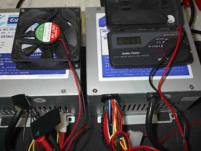
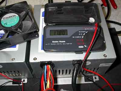
Let's run a test of my two supplies in parallel using a 12 volt fan:
|
|
|
|
 |
|
|
|
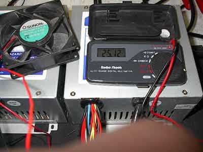
Excellent, almost 13 volts. These two power supplies are laughing at me I am sure. Ok, how do we wire these supplies in series? I am going to refer to the supplies as supply1 and supply2 for reference. This is a little more difficult, but not too tough. First, we take the peltier and connect the positive end of the peltier to the positive (yellow wire) of supply1. We then take the negative (black wire) of supply1 and connect that to the positive (yellow) of supply2. Then we take the negative (black) of supply2 and connect that to the negative of the peltier. See, not too tough. Make sure you follow the directions correctly though or you chance shorting your supplies. Let's see what kind of voltage we get in series with two 12 volt fans in series as well: (note: there are two 12 volt fans in series, otherwise, I would fry that fan running at 25 volts!)
|
|
|
|
 |
|
|
|
25 volts! I know a lot of you are hitting TE Distributing right now buying up those 24 volt 172 watt peltiers . At 24 to 25 volts, it may not run as efficient as say 18 volts, so let's see what kind of voltage we get when we run the +12v (yellow wire)of supply1 in series with the +5v (red wire) of supply2. To do this, we just substitute the red wire of supply2 in place of the yellow of supply2.
|
|
|
|
 |
|
|
|
Good enough. Almost 18 volts. From what I hear, that's what those 24 volt peltiers run the most efficiently at anyways. I have in my possession two Sparkle 300 watt AT supplies that have voltage adjustments on the circuit board and I think I would be able to easily get at least 18 volts from the two of them. As for those of you who plan on constructing water chillers using four to eight peltiers, you may be in luck as well. You can run in parallel or series as many power supplies as you want as long as you perform the modification to all but one of the supplies. Let's say you plan on running four power supplies in parallel providing 12 volts at 40 amps. You would have to perform the modification to three of them.
I must thank August Hoecker for his expertise and help in providing this power supply modification. He was very eager to help me with this and has written an article on how to do it for amateur radio operators. It can be read here: http://www.antennex.com/preview/archive3/powers.htm
Whether he knows it or not, he has provided a lot of us power hungry overclockers with the solution to our power supply problems. The 24 volt peltiers are now a reality. To top it all off, I can mount these supplies in my tower. I know a lot of you are wondering what kind of results I got with the new AXIA chip and 172 watt peltier. Well, we'll just save that for the next article, won't we. =]
Ondaedg is out!
|
|
|
|
That about wraps this article up, If you have Questions please post them on the ProCooling Forums (recommended), or Email OnDaEdg directly.
|
|
|
Articles Home |
|
|
|
|
| Random Forum Pic |
 |
| From Thread: Fairly Large Project: Oil+TEC Tank PC |
|
| | ProCooling Poll: |
| So why the hell not? |
|
I agree!
|
 67% 67%
|
|
What?
|
 17% 17%
|
|
Hell NO!
|
 0% 0%
|
|
Worst Poll Ever.
|
 17% 17%
|
Total Votes:18Please Login to Vote!
|
|


