|
|
|
|
 Testing PC cooling using die simulators vs. real CPUs Testing PC cooling using die simulators vs. real CPUs
|
|
Date Posted: Dec 14 2005
|
|
Author: pHaestus
|
|
Index:
|
|
|
Posting Type: Article
|
|
Category: FAQ's, Editorials, Q&A's
|
|
Page: 3 of 4
|
Article Rank: from 2 Readers
Must Log In to Rank This Article from 2 Readers
Must Log In to Rank This Article
|
|
Forum Discussion Link
|
|
|
|
Testing PC cooling using die simulators vs. real CPUs By: pHaestus
|
Rationale for using a CPU
While there are clear reasons for using a die simulator in R&D type testing, performing tests with the actual CPU as a heat source is not without merit either. The fundamental advantage to using a CPU is that it’s not a simulation; it’s the actual heat source we’re interested in.
Is a copper slug a good simulation of a CPU? Not really. Consider that the processor is connected to a large amount of copper not only at the die area, but also at the pins (the motherboard traces). Consider all the secondary heat sources and cooling paths around the motherboard’s socket. Consider the many types of computational operations which generate heat in different parts of the processor. Obviously a copper die is only a crude simulation of the real heat source. As a tester, it’s a lot easier to convince readers that results on a real CPU are relevant to their PC compared to the results from testing with a roughly CPU-shaped hunk of copper. Finally, both Intel and AMD have provided guides to thermal testing for their processors for many years that typically demonstrated their preferred methods of testing coolers with modest instrumentation.
Limitations and Problems with CPU-based Testing
There are several obstacles one must overcome when testing with real CPUs. A major drawback to using a CPU for your testing is that the motherboard’s onboard temperature monitoring system is utter junk. Not only is the resolution poor, but the diode readings are VERY sensitive to electrical noise and motherboard design. Motherboard designers have more important things to worry about than the accuracy of the temperature reading for the CPU (+/-10C is probably fine from a design standpoint anyway) and it shows. There are ways around this, but they involve risky CPU modifications. I’ve had lots of fun soldering wires in the place of AMD CPU diode pins and then directly reading the temperature from the core using a Maxim diode reader. You can still do this on AMD64 CPUs, but the soldering is more difficult. The finished product is also a lot more fragile than a copper die simulator (yes even with flatness issues).
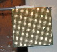
One of my major problems with an AMD64 is the fact that when you change coolers, the CPU is prone to ripping out of the socket. This is a problem for everyone, but when you have delicate wiring soldered directly onto the solder pads of your socket 939 CPU it’s an even larger concern. The new Socket 775 packaging from Intel addresses this problem by using a “pinless� CPU and a clamping/restraint system that directly restrains the IHS. For AMD systems, one could simply take the IHS off an AMD64 CPU and test with a bare core. This solves the above problem, but now our CPU has lost its real world viability for the vast majority of readers. Another limitation of diode readings for cooler testing is that no such external CPU diode monitoring exists for Intel CPUs. In fact, it is documented that the diode reading externally accessible to monitoring software is NOT in the hot part of the CPU and instead that a second diode is used for CPU throttling and other important purposes.
For newer CPUs with an IHS, it is possible to machine a tiny groove into the IHS and then use a thermocouple to collect the temperature of the IHS. This isn’t a direct measure of CPU die temperature, but presumably it is directly related to the die temperature. This provides some of the benefits of a die simulator (good temperature resolution and accuracy) on a real processor. The drawback is that it is obviously not the core temperature of the chip and very subject to error from positioning changes and probe placement when installed. Presumably the probe will be fixed into the groove and so it will be in a constant position after installation. I am also not sure this addresses the tendency of a CPU with heatspreaders (other than Intel 775) to rip out of the socket when coolers are changed.
Another problem with heatspreaders is the thermal interface between the CPU core and the IHS. For modern Intel CPUs, the IHS is soldered into place and should be fairly stable. For AMD CPUs, however, a thermal interface material (TIM) bridges the space between the core and the spreader. This TIM can degrade over time, which will impede heat transfer from the core to the IHS and the cooler. If this happens as expected then we are no longer accurately evaluating cooler performance, and instead we are monitoring the deterioration of that thermal joint over time. How significant is the deterioration in performance? I do not know. What is clear is that the TIM joint between the heatspreader and core presents a significant thermal resistance that may change over time. This is bad news for testers, and makes AMD CPU performance testing with IHS a poor choice for any cooler R&D.
Another problem with CPU testing from a reviewer standpoint is one of hardware longevity. As my Socket-A testing continued for a year, I fried a motherboard and a CPU or two. Any hardware change was accompanied by a lengthy recalibration/revalidation process that took about 2 weeks. And eventually it becomes very difficult to obtain replacement parts for your system. A final problem is one of long term relevance. In late 2005, would you consider a new waterblock test on my fully functional Socket A test platform relevant?
As a final issue, I would point out that as a quantifiable heat source, a CPU is pretty poorly suited to testing. It’s possible to estimate W from water and flow measurements, but most reviewers simply have no idea how much heat has been actually applied in their testing. One can extensively modify the motherboard to read current, but this is a seriously complicated project. And the voltage regulation of your motherboard may be somewhat affected by time, especially if you are overclocking the system and stressing the electrical components. A related question is how do you produce heat from the CPU? Every popular CPU heating program has its own code that may heat CPUs to a different extent. This has been well-established from our testing.
The Intel TTV
Intel has produced a thermal test vehicle (TTV) for several years to provide a heat load that have correlated to the power that their processors generate. This is a heat source that is specifically designed by Intel to be representative of thermal loads of their CPUs, and it is incorporated into a mock motherboard with proper socket placement. Is it still a simulator? Yes but presumably it is much closer as a heat source to a real CPU. Unfortunately, I cannot comment too much on the pros and cons of the TTV as they are not available to end users and reviewers. They seem at a glance to incorporate most of the benefits of a die simulator (quantified heat source, acceptable temperature resolution using type t thermocouple) with most of the benefits of a CPU-based system (mounting on a real motherboard, die face identical to real CPUs). It is my understanding that the only temperature accessible with the TTV is a "cpu case" temp obtained with a thermocouple in the grooved IHS. The only TTV-based waterblock testing I am aware of originated from Swiftech, who have been using an Intel TTV for their newer cooler performance evaluations.
|
|
|
|
|
| Random Forum Pic |
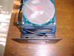 |
| From Thread: My External WC rig completed |
|
| | ProCooling Poll: |
| So why the hell not? |
|
I agree!
|
 67% 67%
|
|
What?
|
 17% 17%
|
|
Hell NO!
|
 0% 0%
|
|
Worst Poll Ever.
|
 17% 17%
|
Total Votes:18Please Login to Vote!
|
|


