|
|
|
|
 Supercooling and Insulation Supercooling and Insulation
|
|
Date Posted: Jun 2 2000
|
|
Author: Rich W
|
|
|
|
|
Posting Type: Article
|
|
Category: High End Cooling
|
|
Page: 2 of 3
|
|
Article Rank:No Rank Yet
Must Log In to Rank This Article
|
|
|
|
|
Note: This is a legacy article, imported from old code. Due to this some items on the page may not function as expected. Links, Colors, and some images may not be set correctly.
|
|
|
Supercooling and Insulation By: Rich W
|
|
Super Cooling and Insulation
|
|
|
|
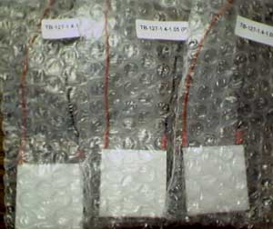
Here they are, the three 84 Watt peltiers that I
currently use. I got them from www.tedist.com, and
they are potted. Potted is the only way to buy
peltiers. If you don't get a potted peltier, you are
really asking for trouble.
|
|
|
|
|
|
So that's the background/components of my cooler. Now I will show some of the materials and how I used them in creating the insulation.
|
|
|
|
|
|
|
|
|
 |
|
For insulating foam, I used Foamies(tm) brand foam. This stuff cuts very nicely and doesn't "break" like Styrofoam does. It comes in two thickness': 2 mm and 1/4". This stuff is flammable, so don't expose it to any flame or large amounts of heat. This stuff can be found at Wal-Mart and many craft stores, and is available in many different colors (purple, pink, black, green, white, etc...), and is available in sticky-back versions (only 2 mm, I think).
|
|
|
|
 |
|
|
|
|
|
To hold things together, I used "Aleene's Original Tacky Glue" (please forgive
the 3 color banded streaks, it's actually in a gold colored bottle...). I've heard
from one person that this glue is soluble in water, but I'm not sure. I've not had
any problems with it, and it holds my insulated box together quite well.
|
|
|
|
|
|
Pictures/Diagrams of the Insulated Enclosure
|
|
|
|
Here I will show you diagrams and actually pictures of my insulated enclosure. I have found this design to be very effective in combating condensation (I currently run my CPU at about -25 deg C).
|
|
|
|
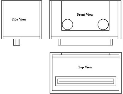
Here are side, front, and top views of the insulated box. All sides shown here are 1/4" foam. The gray lines indicate sides of the foam that are obstructed from view. The piece of foam with the holes in it is not attached to the main enclosure, instead it is "stuck" to the water jacket with Vaseline, and then is slid down into the box, and again greased with Vaseline to ensure a good air tight seal against the box. The little lip protruding down actually slides over the slot 1 interface so that no air can come into contact with the colder slot. Again, Vaseline is used to seal out the air. Notice the slit in the top view. This is where the CPU's edge connector stick out of the box and into the slot. Also, in reality there are 2 holes in the bottom of the box which allow the bolts from the plastic "bridges" to pass through. Washers are backed against both sides of the foam and smashed together with nuts... of course, Vaseline is again used to seal out the air.
|
|
|
|
|
|
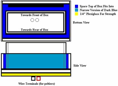
I hope you can make at least a little sense of this picture. Some of the things shown here are NOT implemented in the actual photos below (they are a little outdated... ), however the basic idea is simple. These diagrams show the lid of the insulated enclosure. It is designed to fit snugly over the top of the insulated box. The differences in the diagrams and the actual photos is that the diagrams (and current version I am using) also have a layer of foam around the sides of the top so that it makes better contact with the box, therefor greatly diminishing the risk of condensation (I found that I needed this extra layer the hard way, unfortunately.. toasted a vid card and almost got my network and SCSI card :/). The yellow is a piece of 1/4" Plexiglas I added to the top piece of foam to give support when I hook up the wires to the terminals (they are "push operated", so I have to press fairly hard and without the Plexiglas, this would destroy the foam). Again, all of the surfaces here are coated in Vaseline to maintain a good air tight seal with the insulated box.
|
|
|
|
|
|
|
|
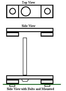
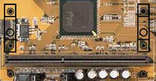
These are the "bridges" that allow me to mount this 4
pound water jacket and all of the other weight, etc.,
that comes with such a large cooling solution. You
can see the placement of the "bridges" on the two
holes to the right of the slot 1 mounting holes (this is
not my motherboard, BTW). Unfortunately, this
method of using a foam box (atleast in my design),
partially covers up the heatsink of the chipset and it's
temp rises slightly.
In the first picture, you can see that the third diagram
shows the bridges mounted to the motherboard. This
is accomplished by using a #8-32 tap on the holes
that are used to mount to the motherboard. Nylon
bolts are then used to screw from the bottom side of
the board into the plastic bridges.
|
|
|
|
|
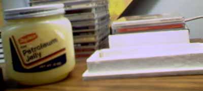
This thing rocks so much, Better get out the Vaseline!
|
|
Joe : Well we all knew serious cooling, fast machines, The Net, and Vas just went together naturally :)
|
|
|
Here it is. The almighty Vaseline. You can see it here next to the lid (which is at this point coated with Vaseline, as you can barely make out the clumps of the slippery stuff on the sides of the lid). In addition to coating most of the insulation surfaces to achieve an air tight fit, I stuffed as much of this stuff in the slot 1 as I could fit. This displaced the air inside the slot so there would be no condensation on the pins of my Celeron 400. This is O.K. because Vaseline is non conductive (both thermally and electrically), and is non corrosive. I've seen people now use dielectric grease, but I've known people to use Vaseline for this purpose long before.
|
|
|
|
|
|
Heaters?... I thought we were trying to cool this thing?!
|
|
|
|
|
|
|
|
|
|
|
|
|
|
 |
|
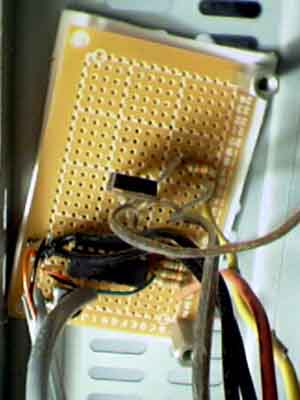
This is the heater circuit. I will publish a schematic
soon. However, this circuit works by checking the
temperature difference between the ambient
temperature and the temperature of the slot 1
interface. When the difference is more than an
adjustable amount (via the variable resistor), a bank
of six 1/4 Watt, 10 (??) Ohm resistors around the
slot turn on until the temperature of the slot is greater
than the ambient.
|
|
|
|
 |
|
|
|
|
|
In the second pic, you can see the wires from the
heater circuit above going down to the slot: one is
the thermistor lead while the other is the hookup wire
for the resistor bank.
|
|
|
|
|
|
 |
|
|
|
|
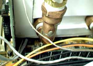
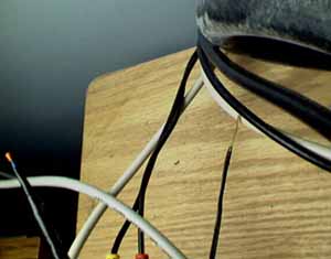
In the third picture, you can see the back of my PC
with a few cables and the water lines sticking out.
You can also make out two thermistor probes - one
is the standard thermistor that came with my Abit
BX6-R2, the other (small orange glob with blue
leads and black electrical tape) is the thermistor
which monitors the ambient temperature for my
heater circuit.
|
|
|
|
|
|
|
|
| Random Forum Pic |
 |
| From Thread: via aqua thread size |
|
| | ProCooling Poll: |
| So why the hell not? |
|
I agree!
|
 67% 67%
|
|
What?
|
 17% 17%
|
|
Hell NO!
|
 0% 0%
|
|
Worst Poll Ever.
|
 17% 17%
|
Total Votes:18Please Login to Vote!
|
|