|
|
|
|
 Reading from the Athlons on-die thermal diode Reading from the Athlons on-die thermal diode
|
|
Date Posted: May 22 2002
|
|
Author: pHaestus
|
|
|
|
|
Posting Type: Article
|
|
Category: Hardware Modding
|
|
Page: 2 of 2
|
|
Article Rank:No Rank Yet
Must Log In to Rank This Article
|
|
|
|
|
Note: This is a legacy article, imported from old code. Due to this some items on the page may not function as expected. Links, Colors, and some images may not be set correctly.
|
|
|
Reading from the Athlons on-die thermal diode By: pHaestus
|
|
Comparison to other CPU temperature measurements
|
|
The primary reason everyone is so excited about using internal diodes for CPU temperature methods is that other options are generally pretty awful. Socket probes on motherboards are very variable in performance. Some reach the back of CPU but are bulb type and make poor contact. Others don't even make contact with the CPU's base, either being bulb thermistors that are too short or else PCB mounted thermistors. In all cases, 10k thermistors are typically used, which are NOT ideally suited for the temperature range of CPUs (3C accuracy is typical). To try and obtain CPU temperatures less dependent on the motherboard, many users emply a flat thermistor (Compunurse) taped to the side of the CPU core. This reading is often slightly better, but still subject to lots of variability. Again the accuracy is likely to be 3C (although resolution is 0.1), and it is impossible to place the compunurse in the same position with the same amount of thermal paste between it and the core reproducibly. Variations in temperature that are a result of mounting the compunurse probe may often be larger than differences in heatsink performance. Other than reading from the diode, using an accurate temperature probe (thermocouple) epoxied under the center of a ceramic CPU is the only method for measuring CPU core temperatures recommended by AMD. You can find a guide to taking temperatures in this manner here at Pro Cooling.
|
|
|
|
|
|
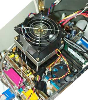
Since I have a Morgan core Duron with a ceramic base and internal diode, I thought it would be useful to perform some correlative experiments by measuring the CPU back temperature along with the AMD internal diode. To accomplish this, I epoxied (Arctic Silver epoxy) a Dallas 1 Wire temperature probe (DS18B20) under the center of the CPU core and attached it to the Crystalfontz 633 lcd. The CF 633 has 0.125C resolution and 0.5C accuracy, so it is useful when comparing smaller temperature differences. Additionally, one can chain many DOW sensors to measure temperatures in many useful spots. This is difficult to accomplish otherwise.
|
|
|
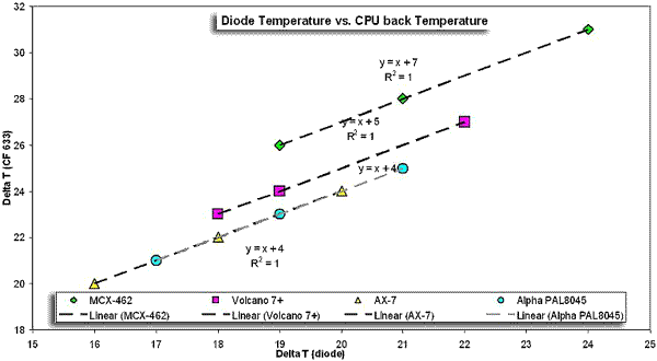
For the comparisons, several heatsinks were tested at 3 different fan voltages (the results of this testing will be compiled in a heatsink comparion that will be done soon). The CPU was placed under load with CPU Burn (K7Burn) at high priority, and intake air temperature (air temperature 1" above the fan on the heatsink), CPU diode temperature, and CPU under temperature were all collected. Below are the results.
|
|
|
 |
|
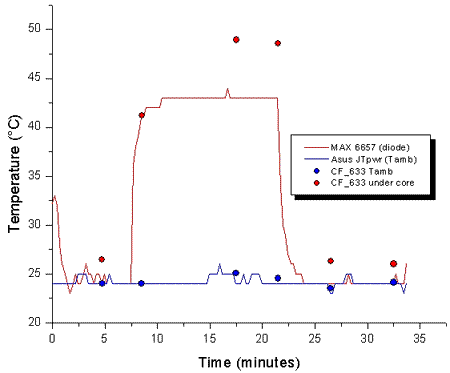
One can see that there is a perfect correlation between the diode temperature and the CPU under temperature for every heatsink. However, the intercept of the line is different in many cases (although the alpha and the ax-7 are identical). This suggests that airflow around and under the socket has an effect on the relationship between the CPU under temperature and the diode temperature. This is not surprising if you consider that the CPU under temperature is an indirect reading that is affected by secondary cooling paths and the air temperature in the socket. More disturbing is the observation that the CPU under temperature is consistently higher than the CPU diode temperature. As the CPU's heat originates in the die, there is no good reason that the temperature far from the die would be higher than the temperature in the heat source itself. You can clearly see the higher temperatures when a run of the testbed is plotted:
|
|
|
|
|
 |
|
|
|
|
The observant reader will probably conclude that the diode temperatures appear to be compressed relative to the CPU under temperatures. There are several reasons one could concoct for why this is a real effect. Perhaps the CPU's "heat producing bits" are located much closer to the ceramic base than to the diode. Perhaps the diode is located on the edge of the core and therefore is cooled by secondary paths. Perhaps the insulative properties of the ceramic base lead to heat being trapped and higher temperatures further away from the heatsink. This same effect (diode temperatures that are lower than the CPU back temperature) can be seen in JoeC's testing where he posts both numbers as well, so it seems pretty consistent.
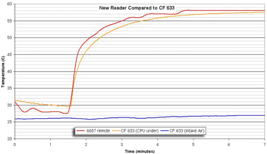
I would however contend that there is a much simpler explanation. According to AMD's Tech doc #24228, diode temperatures are decreased from 0.4-0.8C per W of resistance in the wire. I believe that this is the explanation for the observed temperature compression of the diode. I have had a lot of trouble soldering twisted pair onto the socket (and the reader), but I recently constructed a new reader with all wiring being done using twisted pair from a CAT5 cable. Careful care was taken to get a good solder joint at the socket's pins, with direct contact between the wire and the pins on the backside. The leads were soldered directly to the reader rather than using a 2 pin header to further eliminate any resistance. You can see from the results below that this made a big difference:
|
|
 |
|
|
This looks much more reasonable; the CPU diode temperature is now about 1-2C higher than the CPU back reading under load. Interestingly, the fact that the CPU back temp reading is higher than the diode reading is also consistent with the AMD technical document. The diode numbers still actually look a little low if you run them through AMD's equation for comparing the CPU back temperature with the diode temperature. By that calculation the CPU diode temperature should actually be about 60C and not 58C as in these results. But there could be some discrepancy in measuring the CPU back temp with a sensor in a transistor type package with a lot of plastic on its backside as well. The important thing to note is that the quality of the solder point between the CPU socket and the lead wires WILL AFFECT your results, so be careful. When you get a proper joint, the solder will glaze over and shine. A poor joint will be dull in appearance. Also try moving the wire around a little and make sure that it is solidly attached.
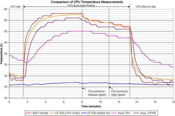
As a final graph, I tested a Volcano 7+ heatsink at three different fan speeds (low, medium, and high speed) on my test CPU. I placed a flat thermistor on the JT PWR header, and recorded CPU temperature from the internal diode, CPU side (the flat thermistor), CPU back (the CF 633), and the motherboard's socket CPU thermistor. The results were obtained by letting the system idle (with WPCredit forcing a true idle state) and then putting the processor under load with CPU Burn at high priority. After the load temperature was reached at low speed, the fan speed was adjusted to medium and allowed to reach the new load temp. After that the fan speed was increased to "high" and the system again allowed to reach the new load temp. Finally, CPU Burn was turned off and the system was returned to idle.
|
|
 |
|
|
I think that this graph probably has about as much information as you should ever put in one place. There are several important things worth noting. First of all, the Asus CPU probe is utter crap (no surprise there though). The flat thermistor on the side of the CPU doesn't do too badly, but consistently underreports the true CPU temperature. The other thing to consider about the flat thermistor is that its response time is much slower than either the CPU back or diode readings. The CPU back temperature is a reasonable approximation to the diode temperature, and I would recommend this approach to anyone still using a ceramic Tbird processor. You can still see some delay in temperature increase and decrease with the CPU back reading caused by heat having to travel through the ceramic base of the processor.
|
|
|
Conclusions and Remaining Questions
|
|
There have been complaints about the supposed non-linearity of AMD's diode that I hope this article somewhat addressed. The problem lies not with the diode embedded in the CPU but rather with the construction of the diode readers. With careful design and implementation, it is possible to use a diode reader very effectively.
I did not discuss the performance of motherboards with onboard diodes because I don't own one. I would be very interested to see the linearity C/W values obtained with the diode and varying heat loads on these motherboards. It is possible that while they do read the diode that specs were not carefully followed with respect to crossing over layers of PCB, thickness of traces, and trace length. All of these parameters have the potential to affect the diode temperature reading tremendously. For motherboards that are basically slight tweaks of older boards (some KT333 mobos bear remarkable resemblance to their KT266 forebears) then this will likely be an issue.
The same problems are certainly an issue for those who try and modify their motherboard's Winbond IC to read from the diode. This is certainly possible, but I would encourage those of you doing this to cut the legs from the Winbond IC and simply hotwire in jumper wires and the needed resistors and capacitors rather than trying to work with the problematic existing traces.
A final thing that I want to mention is the fact that many of these Maxim ICs have other useful features that you may want to incorporate. For example, the MAX6657 has an Alert and an OverTemperature function that can send an alarm over the SMBus and also can perform a task if the diode rises above a preset value. This could easily be wired to create a circuit that would shut down power to your system if the CPU temperature became too high.
|
|
If you have any comments or Questions please email me at pHaestus@ProCooling.com
|
|
|
|
| Random Forum Pic |
 |
| From Thread: Another #Rotor style block... |
|
| | ProCooling Poll: |
| So why the hell not? |
|
I agree!
|
 67% 67%
|
|
What?
|
 17% 17%
|
|
Hell NO!
|
 0% 0%
|
|
Worst Poll Ever.
|
 17% 17%
|
Total Votes:18Please Login to Vote!
|
|