|
|
|
|
 The Rock The Rock
|
|
Date Posted: Sep 27 2001
|
|
Author: Unaclocker
|
|
|
|
|
Posting Type: Article
|
|
Category: ProCooling Projects
|
|
Page: 3 of 5
|
|
Article Rank:No Rank Yet
Must Log In to Rank This Article
|
|
|
|
|
Note: This is a legacy article, imported from old code. Due to this some items on the page may not function as expected. Links, Colors, and some images may not be set correctly.
|
|
|
The Rock By: Unaclocker
|
|
|
|
|
Project : The Rock
|
|
By: UnaClocker 9/27/01
|
|
Cooling Design - (cont.)
|
|
|
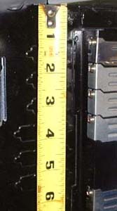
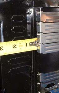
While wracking my brains for a place to mount the reservoir, I started measuring any open spaces in my case that I could find. I hadn't received the reservoir, but Tower Hobbies, with whom I'd placed the order, had the measurements on their site.
|
|
|
|
|
|
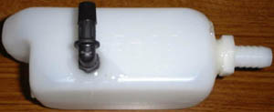
The tank measures roughly 6"x2". As you see here, I have a perfect spot for that tank right here over the I/O ports on the motherboard. I've since compared other cases, including Little Stealth, and found that almost all cases have this nice spot. I think this was one of the most innovative ideas of this whole project; mounting the reservoir right here. I still didn't have the tank, but now I had something new to incorporate into my drawings.
|
|
|
|
|
|
|
|
|
|
|
|
|
|
|
|
|
 |
|
This drawing is much more simplistic, I just simply wanted to see the routing of the hoses. This is the final design I used, I ended up using 7 90 degree fittings to route the hose cleanly. I had also heard a rumor that running larger intake hose than output hose would help the flow, since the pump wasn't designed to suck, just pump. So I ran 1/2" from the bottom of the reservoir, into the pump. It came out of the pump and took and immediate turn to the "back" or right hand side of the case, then took another turn up the side of the case. This would hide most of the hose from the view of the window, it'd be behind the drives, when it got up to the height of the radiator, it took another turn, and into the radiator. After leaving the radiator, it'd take a 90 and angle down to the block, where yet another 90 would turn it down into the block. It would then leave the block, and take one last turn into the reservoir.
|
|
|
|
 |
|
|
|
 |
|
|
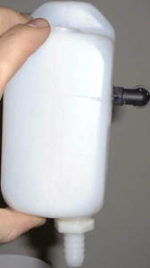
The day the reservoir arrived was a big day because that was the last part I was waiting for before assembling the entire system. The reservoir had only the top fill hole when I'd received it. I used a drill to make the holes for the barbs. I didn't have a tap to tap the holes, so I just made them slightly oversized. I had originally planned to use Plumbers Goop to glue the fittings into the reservoir. Unfortunately, I had no luck locating any at the local stores, so I went with epoxy instead. This worked, but I had to re-do it a couple times. The plastic would flex but the epoxy wouldn't which caused it to become unattached. Not a good thing when I need a water tight seal. A problem I found about 2-3 months down the road was that the epoxy was not at all happy with the UV given off by my blacklights. It quickly turned a nasty yellowish color, which you'll probably see in some of the pictures later in this article.
|
|
|
 |
|
|
|
|
|
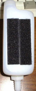
Now, to hold the reservoir to the side of the case, I used self adhesive Velcro. This worked ok, but the adhesive wasn't strong enough to hold the weight of the water, so I ended up reinforcing it with zip-ties.
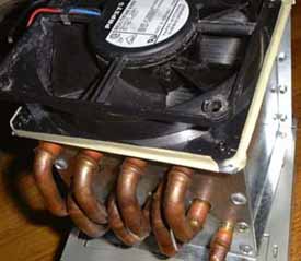
Next came the radiator and fan. You may have seen how I mounted the fan to the radiator already if you remember my review of the radiator. Here are the pictures again, if you've forgotten.
|
|
|
|
|
 |
|
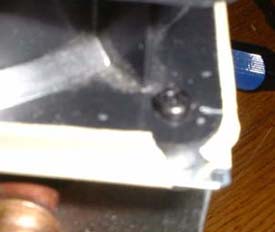
I used small screws from old pentium heat sinks to hold the fan to the radiator and masking tape to seal the seam around the fan. The masking tape would be completely hidden from view when mounted in the case, so it wasn't a problem as far as how it looked.
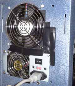
I also had to cut out a circular hole for the fan in the back of the case. This is something I should have done before painting the case, but hadn't. I believe I hadn't gotten the radiator yet, so I wasn't exactly sure where to place the hole.
|
|
|
|
 |
|
 |
|
|
|
I used some electrical tape to cover the gaps left over from the original power supply's holes in the back of the case. Not the most ideal solution, but the back of the case is very rarely ever seen.
|
|
|
|
|
|
Now before we get to installing the motherboard, running all the hoses, and filling the system, there's another major piece of this puzzle that needs completing. The wiring.
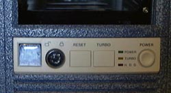
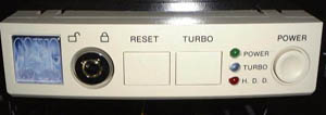
So I'd like to take a break from plumbing, and move into wiring. Let's start with a shot of the front "control panel" on the case.
|
|
Wiring and Electrical work-
|
|
|
|
This case, being an AT case, had a turbo button, turbo light, and a key lock on it. These are things you almost never find on an ATX case. It also had an AT style power button. I wanted to wire-up the turbo button and LED into a simplistic fan-bus. Press the turbo button, and the radiator fan would wind up to it's normal 12v, and the turbo LED would come on. Press it again, and the fan would wind down to 7v, and the LED would go off. Fairly simple to do with a DPDT switch, which is exactly what the Turbo switch is.
|
|
|
|
|
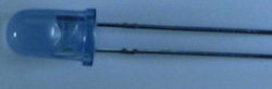
I also wanted to make the turbo LED blue. A lot of people will run blue LED's everywhere: the power, hard drive, everything. Blue LED's are nice, but it's also nice to be able to see from a distance exactly which lights are on. If they're all blue, it's harder to tell what's on. The problem I had here was that the
|
|
|
|
|
|
|
|
|
|
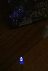
LED's are square and it's very difficult to find square, blue LED's. I scrapped the idea within a day and decided to drill out the holes and run round LED's. Another pet peeve of mine is how bright the average blue LED is. I'm not trying to light my bedroom with these LED's; I'm just using them as an indicator light. Luckily, Radio Shack had just the item for this job; "Diffused blue" LED's. So I ordered one of those, along with 1 red and 1 green LED. If you've never seen a diffused blue LED before, here's what they look like
|
 |
|
|
 |
|
|
|
|
|
And here's how the panel looked after I installed the bulbs.
|
|
|
|
|
 |
|
|
You have to get really close to see that the case originally had square LED's. Now came the turbo switch wiring.
|
|
|
Let's just say that it wasn't easy. I had to run power up from a Molex connector, 5v and 0v. Then I had to hook the 0v and 5v into one side of the switch. The negative line ran out to the fan so that the switch would 'switch' the negative on the fan between 0v (for 12v operation) and 5v (for 7v operation). At the same time, I had to run 5v to the other pole of the switch for the blue LED. I had to make sure that power got to the LED when the switch was in the 0v DC position. I also wanted to make sure that the switch was in 12v mode when pushed in and 5v when it was out. I had to put a resistor between the 5v and the blue LED and I had to hook the other side of the LED to 0v; Quite a bit of wiring to keep straight. The key lock switch was wired into the black light to act as a power switch. I'll cover that next.
The last thing I needed to do was the power switch. I don't have any pictures of this, but it was pretty straight forward. There's a pin in AT style power switches that holds it in the ON position when you press it and lets go when you press it again. Well, when you yank that pin out with a pair of pliers, the switch becomes a momentary switch, and it won't stay in the ON position. This was perfect for an ATX system. From there I simply had to solder some wires onto the switch and run wire down to the motherboard with a jumper style connector at the end.
|
|
|
|
|
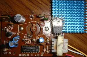
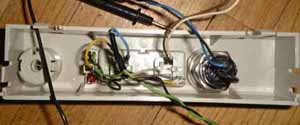
Now comes the internal lighting. As you may remember from project Little Stealth 2, I had some nice little black lights from Allelectronics, 5" fluorescent black lights that were only $5 each. (They are probably still selling them, but I haven't looked lately). In LS2, I had the circuitry inside an air duct to keep it from over heating. With this system, I didn't have any air ducts to install it in, so I just put a larger heat sink on it and then mounted it out in the open. At the same time, I got a second circuit so that I could put in a white light. I haven't come up with a place to put the switch for the white light yet, unfortunately.
|
|
|
|
|
Here's a shot of the huge heat sink I put on the transistor. Needless to say, it now runs cool even without a fan. I used Arctic Silver epoxy to attach it. That stuff works wonders for attaching heat sinks to just about anything. Definitely a must-have for any overclocker. I mounted the circuitry on the right side of the drive bays way up out of the way where it can't be seen from the window at all. No point in showing any pictures of that since the wiring is atrocious back there. I mounted one bulb right next to the reservoir and one right along the bottom of the case. You'll see those when I get to filling the hoses; I don't want to spoil the surprise. There are two concerns that people have brought up concerning my lighting. The first issue is the heat generated by black lights. This is coming from the people that have only used incandescent black lights like the kind you screw into a normal light socket which gets hot enough to fry an egg on. Fluorescent black lights don't get that hot. They hardly get warm to the touch half the time. So the heat generated by these 2 bulbs is very minute. Each bulb only uses about 5 or 6 watts. Another big concern is the RF interference emitted by fluorescent bulbs. All I can say is that I've not had any problems with system stability with the lights on.
As for the white fluorescent light I installed, I put that in about 3 months later, so I'll cover that more later on.
The only wiring remaining to be dealt with is with the two intake fans. I just ran a wire from the Molex connection that went up to the control panel (and eventually onward to the radiator fan, along with the fluorescent lighting) down to the fans. They run so quiet that I didn't see a need to vary their speed.
|
|
 |
|
|
|
|
|
|
|
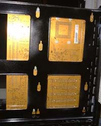
It turned out that the holes on the motherboard tray lined up perfectly with the holes in my motherboard. This was on of my big worries. I was extremely surprised by this, but in a good way.
|
|
|
|
|
 |
|
|
 |
|
|
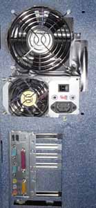
These two shots show the back with the motherboard in place. As you can see, it's a very tight fit getting to the keyboard and mouse ports, but it's not as bad as it looks in these shots. I used Epoxy rather than screws to hold the ATX back plane in place. I ended up regretting this because the Epoxy came off of the metal on the case and took a large chunk of the paint with it. I still haven't gotten around to redoing that with actual screws.
|
|
|
|
|
|
| Random Forum Pic |
 |
| From Thread: Solid State 12v DC Relays $10.00 ea. |
|
| | ProCooling Poll: |
| So why the hell not? |
|
I agree!
|
 67% 67%
|
|
What?
|
 17% 17%
|
|
Hell NO!
|
 0% 0%
|
|
Worst Poll Ever.
|
 17% 17%
|
Total Votes:18Please Login to Vote!
|
|