|
|
|
|
 The Rock The Rock
|
|
Date Posted: Sep 27 2001
|
|
Author: Unaclocker
|
|
|
|
|
Posting Type: Article
|
|
Category: ProCooling Projects
|
|
Page: 2 of 5
|
|
Article Rank:No Rank Yet
Must Log In to Rank This Article
|
|
|
|
|
Note: This is a legacy article, imported from old code. Due to this some items on the page may not function as expected. Links, Colors, and some images may not be set correctly.
|
|
|
The Rock By: Unaclocker
|
|
Case Cutting and Metal Work -
|
|
|
|
|
|
|
|
|
|
 |
|
|
|
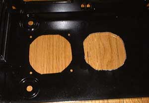
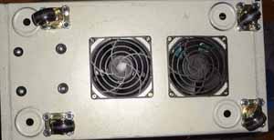
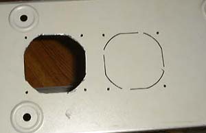
In case you're wondering, the case is upside down in this picture; this is the bottom of the case. I just set the fans in place and drew lines along the inside with a marker. I also put dots in place for the screw holes on the fans. I then used my dremel to cut out the holes. The quality of the cuts REALLY doesn't matter here since it'll be very hard to see from above.
|
|
|
|
|
 |
|
|
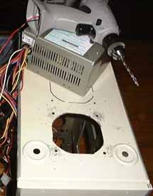
One of the problems I encountered while drilling the screw holes was that the cheap "girlie" drill that I had bought was the cheapest drill they had at Wal-Mart. It, unfortunately, sucked. It was a little battery powered drill, 4.5v, that ran off RC car type batteries. It was just gutless as hell and couldn't drill 2 holes before needing another 16 hour charge. So I did a little UnaClocking on the drill.
|
|
|
|
 |
|
|
|
|
|
Here, I've wired the 5v from a 250watt power supply directly into the drill. This immediately solved my problem. Unfortunately, about 5 holes later, I had toasted the poor power supply. Luckily, the HUGE 300watt power supply that came with 'The Rock' proved to be much stronger and held up just fine. The drill turned out to be very strong when hooked-up to a good power source; though I did have to take breaks with the drill every now and then. I could smell the motor starting to burn out several times.
|
|
|
|
|
|
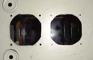
The holes ended up turning out very nice. One of the first things people ask when they find out I have intake fans coming in from the floor is, "Doesn't that fill your system with dust?". Yes, it would normally, but I installed fan filters. I went with plastic ones rather than metal ones. I also found it easier to clean the plastic ones. You might be wondering why I went with 92mm intakes. Well, this case originally came with 2 fans. A 92mm in the power supply and a 92mm mounted in the front pulling air through the grill. I tried them out on my desk and found both of them to be surprisingly quiet, so I decided to use them in the floor. But the main reason I used them was to save money.
|
|
|
|
|
|
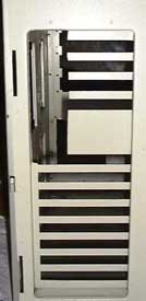
Now I needed to cut out the opening in the back for the ATX back plane on the motherboard. This would be a simple square hole, but I had to measure things out to make sure I got it in the right place. Here's how it turned out:
|
|
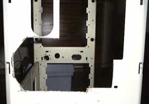
Along the same ATX conversion lines, I needed to cut the hole for the power supply. I used the recently burned out AT power supply for test fitting in the case since it uses the same mounting system as modern ATX supplies.
|
|
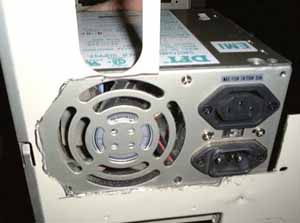
I kind of cut the hole a bit too wide, but that wasn't the main problem. The main problem was that I cut it upside down. My ATX power supply has it's main air intake on the bottom so that it removes the hot air from around the CPU better. Well, with the hole I cut, that intake was pointing the wrong way. Ahh well, live and learn. You might have also noticed that there's a lot of extra space above the supply from the old supply. Most of that will be taken up by the radiator fan, which I'll cover later.
|
|
|
|
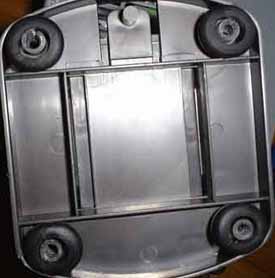
Here I've installed the wheels on the case. These are the same wheels I used in 'Project Little Stealth', part 2'. Cheap, crappy, nasty casters. I've meant to replace them from day one, but for now, they're still in place. These wheels provide the height needed to get good air flow to the intake fans. As you can see, I had to mount them in an unusual way; the original feet on this case went in those big rings. Unfortunately, with these wheels, there was no easy way to mount them on those same rings. I just couldn't drill holes on the outer edges of those rings. So instead, I mounted them just outside the rings as well as I could. It turned out pretty well, I think. You can also see the plastic grills on which the filters sit, installed on the fans. Also seen are the 4 screws that hold the pump in place with rubber washers.
|
|
|
|
|
|
|
|
Under the pump itself, I used rubber grommets in order to keep it from vibrating the metal of the case.
|
|
|
Now we've come to the plumbing part of my article. My plumbing plans for this system went through many, many revisions while I worked out how I wanted to mount everything. My most basic designs were closed loop, and I originally planned to use the "Big Momma" radiator from 'Project Little Stealth 2' in this case but found it undesirable. I used MS Paint to draw up my ideas as I thought of them. It gave me a chance to visualize what the system would look like and allowed my online peers to comment on the ideas.
|
|
|
|
|
This was my first idea. I would just run the hoses up along the back of the case, into and out of Big Momma. Really simplistic, but I didn't like the top mounted blowhole. It just didn't jive well with how I wanted the system to look.
|
|
|
|
My second idea. This was after I had contacted DangerDen, and they had happily agreed to provide me with their cooling cube and Maze2 waterblock to use in a review. Since I already had them, I found that they fit into my plans VERY nicely. So here we have my setup, closed loop.
|
|
|
|
|
|
I really didn't like the closed loop thing. It was a royal pain keeping the bubbles out. After reviewing several waterblocks and having to refill the system repeatedly, I had more than enough water wetter in my mouth to last a lifetime. I became dead set on not going closed loop anymore. In this design, I decided to use a Dubro reservoir, just like Joe used in DH3 and ProMini. I had 3 problems with this setup. The first was that the reservoir blocked my top two 5 1/4 bays from having anything full length in them. I was also concerned about water splashing out while filling the reservoir and rusting the case around the fill hole that I would be soon drilling at the top. And finally, I simply didn't like the look of the big knob on top of the case in DH3 (no hard feelings Joe, looks good on yours, just not my style).
|
|
|
|
|
|
| Random Forum Pic |
 |
| From Thread: product testing today – who is being served ? |
|
| | ProCooling Poll: |
| So why the hell not? |
|
I agree!
|
 67% 67%
|
|
What?
|
 17% 17%
|
|
Hell NO!
|
 0% 0%
|
|
Worst Poll Ever.
|
 17% 17%
|
Total Votes:18Please Login to Vote!
|
|