|
|
|
|
 Airspirits Watercooled Rackmount Part 1 Airspirits Watercooled Rackmount Part 1
|
|
Date Posted: Dec 6 2002
|
|
Author: Airspirit
|
|
|
|
|
Posting Type: Article
|
|
Category: ProCooling Projects
|
|
Page: 2 of 3
|
|
Article Rank:No Rank Yet
Must Log In to Rank This Article
|
|
|
|
|
Note: This is a legacy article, imported from old code. Due to this some items on the page may not function as expected. Links, Colors, and some images may not be set correctly.
|
|
|
Airspirits Watercooled Rackmount Part 1 By: Airspirit
|
|
|
|
|
The airspirit Watercooled Rackmount Project
Pro/Geeks! By: Airspirit 12/06/02
|
|
|
The Hardware: Continued...
|
|
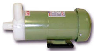
As far as pumps go, there is a broad range of pumps available that pump outrageous amounts of water. This is not a job for a piece of crap Via Aqua 1300, or a low powered Rio, or some other knock-off $20 pump. The radiator alone would bring a Via Aqua to a screeching halt. I currently have a Danner 350 GPH utility pump that I'm going to do my proof of concept runs with (just one computer), and will hopefully last me through the end of Phase 1. The pump I believe I'm going to use come production time (Phase 2 and beyond) is this little jewel:.
|
|
|
|
This is the Gen-X Mak 4 pressure rated pump. It pumps up to 1200 GPH and dead-heads at 23 ft! That will easily push decent flow through my system. Plus, as it only consumes a maximum of 93W, it won't be too much of a draw on my electricity bill, and won't introduce too much heat into my coolant loop (relatively). The reason I'm not going with a stronger pump is that I do not want to be pumping too much heat into the water prior to the coolant making it to the water blocks. As an added bonus, this pump is nearly silent, and in the enclosure of the cooling box, it shouldn't be audible from more than a foot or two away
|
|
|
|
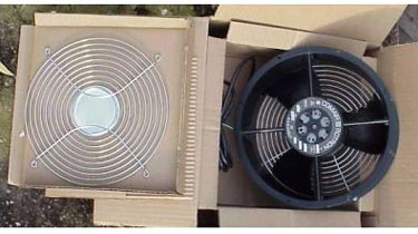
This is a Comair Rotron Caravel 115VAC fan rated at up to 550 CFM, and measuring a meager 10". The added benefit to using this is that it is very quiet. It shouldn't reach over 45 dB, and since it will be blowing through the cooling box, much of the sound will be deadened by the time it exits. It should be quieter than the average 80mm fan used by OEMs. To further deaden the noise, I'm going to add a ceiling fan "dimmer" switch, that'll allow me to slow down the fan and further silence it if it gets a little loud. A nice bonus is the
|
|
|
|
fan guards, which prevents me from turning my fingers into luncheon meat ... which would be the certain outcome if you happened to get caught in this with the metal blades spinning at over 3000 RPM. Finally, something to discourage me from tinkering around inside once I'm done! I will be using two of these side by side in the back of the cooling chest, giving me a net flow of 1100 CFM through the cooler. One thing is for sure: I will have to start looking for a few paperweights, or I will have to contend with my paperwork floating around on the air currents while I work.
|
|
Now that I had all the parts I needed, it was time to finalize my plan for construction. I wanted this system to be as easy to assemble and disassemble as possible. With the ease of draining through the air trap/reservoir, I just needed a way to remove one machine from the system. What I decided to do (after flirting with quick disconnects of all kinds), was use two way hose barb fittings (1/2" to 3/8") to connect between the 1/2" ID hose from the manifolds to the 3/8" ID hose from the internals of the cases. When one machine needs removed, I just need to drain the reservoir, undo the hose clamps to the two-way hose barbs, and pull the hose off, keeping any dripping far away from my precious components (*gollum* *gollum*). The incidental benefit of this is not having to reseat your CPU block every time you mess with your computer's internals.
To do this, though, we need easy draining. Since the tall vertical air trap is a nice gravity well, instead of having a 90 degree bend in the bottom leading inside the cooling box, we will use a T junction, or similar arrangements, with one side going to the cooling box and the other going to a drain valve. Since butterfly valves will be built into the internals of the cooling box (to help prime the pump around the radiator via a bypass line), any coolant left inside of the box will remain there, though all except maybe eight fluid ounces should drain handily.
|
|
|
|
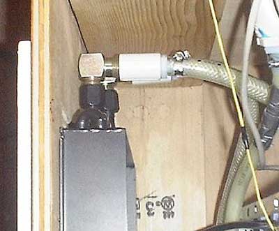
Problem one came when the radiator came in. It has 37° JIC fittings, commonly used in hydraulics. The good part is that this type of fitting is watertight at extreme pressures (since I'm never going to be over 10 PSI, not nearly the thousands the part is rated for, this doesn't apply to me, but is nice insurance nonetheless). The bad part was that they only come in steel, risking galvanic corrosion. In order to fit the radiator into such a short package, I needed an elbow adapter that would also adapt to standard pipe thread. The fittings I bought are treated to be nearly completely inert to corrosion, preventing worries about galvanic corrosion causing failure, though they cost a small fortune.
|
|
|
|
|
|
Problem two is due to the restrictiveness of the radiator. Even the Mak 4 can only pump a maximum of 3.6 GPM through the radiator, though if I was to bypass the radiator and only divert 2 GPM through it (the rest passing from the reservoir directly to the pump), I could get a net flow of almost 8 GPM. That is a 4.4 GPM difference! By putting a valve on the bypass, I will be able to tune the performance of my system to use all of the components to their maximum effectiveness (in this application). Many people believe that this will be an utter failure, and that I will end up just having to leave it closed to get best results. I hypothesize that while I will get higher idle temps this way, my peak temperatures will be lower since the blocks will be working more effectively. We shall see who is right shortly.
|
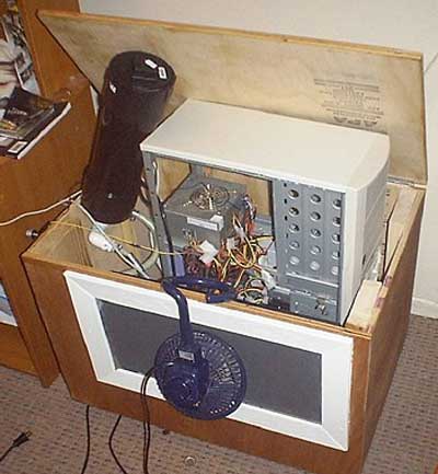
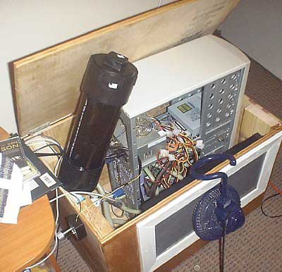
|
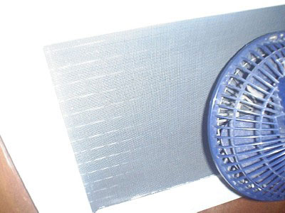
The radiator fit in the box without a hitch, and the fittings were assembled. As an initial test I dumped my old system case and all into the cooling chest and used a desk fan to blow air over the radiator. The "football" sat on top of the whole arrangement. Quite the eyesore. I must admit, though, that this part of the project could have been a show stopper. I didn't remove a single component from my computer case when I did this, removing the radiator from the loop (perched above the motherboard and processor), and moving the pump out of the case. I ended up not spilling a drop (almost dumped coolant on the motherboard twice), but it is not something I will
|
|
|
|
ever do again (though I should never have to worry about a self-contained system again, either). Open hoses with coolant in them do not belong in a case with components. Period.
|
|
|
|
|
|
|
Surprisingly enough, I had a dramatic drop in CPU temps. Previously, using a Black Ice Extreme rev. 2 with two 120mm fans at 12V blowing in a push/pull configuration over it, I hovered at 43C at idle, and 49C at peak use. For a little background, this setup is cooling an Athlon XP 1900+ AGOGA@1880/2.0V. Once I put the Lytron 6320 in the BIX's place with only a weak desk fan blowing across it, I saw my temps plummet to 36C at idle, and 43C at peak use. Since the Lytron wasn't allowed to breathe and still was getting great temps, I knew that this heat exchanger would do the trick for me.
|
|
|
NOTE: Since my computer was in the case with only warm air blowing over the internals (via the radiator) for circulation, my case temps were always around 39-40C, up from 32-34C. Once I get the computer out of the cooling box and into it's new case (on top of the box), this should go back to normal.
Now that the proof of concept with the radiator is complete, it is time to assemble the PVC infrastructure and kick this project off.
By the way, what do you think of the football (that black thing)? It is available for a home if somebody wants it ... it holds almost a gallon of coolant, perfect for priming a rig, and does a passably good job as an air trap. On second thought, I think I'll keep it as a souvenir. It was, after all, my first experiment with working with PVC (complete with a top-end leak from a poor gluing job).
|
|
|
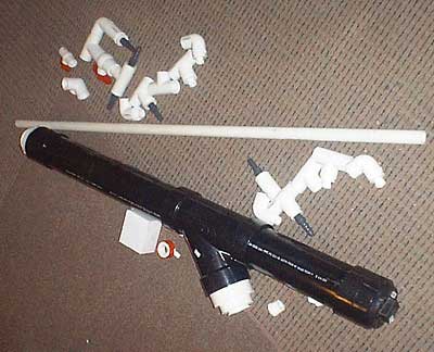
This was an adventure from the start. Over a hundred dollars worth of Schedule 40 PVC was dumped onto my living room floor. I whipped out the primer and glue and got to work. First off, I would like to detail how I glued the PVC. Consider this a how-to for those of you that think you know how this works. I had two types of PVC: the white kind, and the black kind.
|
|
The white stuff requires two types of glue to form a seal. First you apply primer, rubbing the brush around until the PVC starts dissolving and looks milky (do this on both parts on all areas that will be connected), and then you apply PVC glue until the primer and glue are completely mixed (on both parts), and then you slide the parts together and hold on for dear life. It takes a couple of minutes for the glue to set, and it will want to push apart, so you need to hold the joint in place. The seal you just made is now permanent and should never leak. In the places where the PVC and black PVC (ABS) is joined, you need PVC to ABS glue, or you will quickly start leaking. This stuff takes a while longer to set, so make sure the TV is on or something, but you don't need primer for this to work, just the glue.
|
|
|
|
|
|
|
 |
|
|
Ed: Looks an awful lot like a spud gun I used to have :)
|
|
|
|
|
Before you glue PVC, though, just make sure you have thought it through, because once you glue it, you can't go back. The seals you make are VERY PERMANENT.
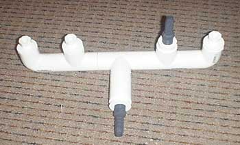
Okay, enough with that, lets show some pictures. First, I made two identical PVC manifolds that splits one line into four. All of the internals of these manifolds are in 1" PVC. Since neither pump (old or new) is designed for over 3/4" flow, this should reduce any resistance from this part of the system. In the branches that aren't use, I'll use PVC plugs and Teflon tape. When it comes time to add
|
|
|
 |
|
|
|
more machines, I just need to unscrew the plugs and put in hose barbs. The process of adding more machines should take less than 45 minutes per machine. How is that for efficiency?
|
|
|
|
| Random Forum Pic |
 |
| From Thread: Danner Mag 3 disassembly & sealing info and impeller/magnet direct coupling attempt |
|
| | ProCooling Poll: |
| So why the hell not? |
|
I agree!
|
 67% 67%
|
|
What?
|
 17% 17%
|
|
Hell NO!
|
 0% 0%
|
|
Worst Poll Ever.
|
 17% 17%
|
Total Votes:18Please Login to Vote!
|
|