|
|
|
|
 Build your own CPU Overheat sensor/shutdown device Build your own CPU Overheat sensor/shutdown device
|
|
Date Posted: May 24 2001
|
|
Author: CK42
|
|
|
|
|
Posting Type: Article
|
|
Category: Electronics
|
|
Page: 2 of 2
|
|
Article Rank:No Rank Yet
Must Log In to Rank This Article
|
|
|
|
|
Note: This is a legacy article, imported from old code. Due to this some items on the page may not function as expected. Links, Colors, and some images may not be set correctly.
|
|
|
Build your own CPU Overheat sensor/shutdown device By: CK42
|
|
CPU Over-Temp Detector / PSU Shutdown How 2
|
|
|
|
Here is where things get a little tricky. I originally had tried to find and use a 'kit' thermal monitoring system. There are a couple out there but I really didn't like the design and the modifications necessary to make it work like it needs to probably would have been more trouble than it was worth. So, what we end up with is something you have to build yourself. Or if you're lucky, you can con one of your electronics geek friends into doing it for you.
The prototype I built didn't take very long…maybe 2-3hrs and that was taking my time to make sure I didn't screw up. Only thing is, I've had more years soldering experience than most people…over 15 years. But, it is possible for the average home hacker to do this….with enough patience. ;)
|
|
|
|
|
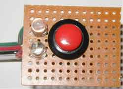
The way that the components are laid out can vary. I'm sure there's probably a more efficient layout than what I used but I was in a hurry to get the thing bread-boarded. The way I did the prototype was to place the momentary switch and LEDs on the remote board. The remote reset board is attached through a 4 wire connector to the main PCB. If you wanted, you could even leave off the LEDs, but having seen the fetish for lights, bells, and whistles out there, I KNOW that ain't gonna happen anytime soon!
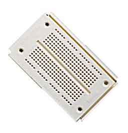
Another thought. If you desired, you could even buy one of the small prototyping breadboards and build the circuit on 'it'. This would be a LOT easier since you wouldn't have to solder anything. The picture to the Left is what I am talking about.
|
|
|
Available at RadioCrack for about $8. If you're not familiar with one of these, the way it works is you put the stripped ends of wires into the holes. All vertical Columns are connected together. The top and bottom Rows are also connected together. This prototyping breadboard would comfortably hold the circuit for this project. I would highly suggest something like this for those not comfortable building a circuit like the one in this article since it makes making mistakes SO forgiving.
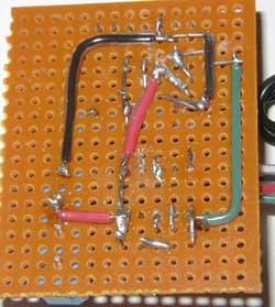
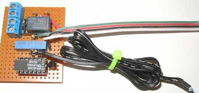
Well, without further ado (what the heck does ado mean anyway?), here's a picture of my prototype system.
|
|
|
|
|
|
 |
|
 |
|
|
|
|
|
The board on the left is the main PCB. The two blue blocks in the upper left corner are terminal blocks. One two pin block is where the PCB will get power from the PSU (Standby Power) and the other two pin block is the connector where the Power-ON signals will attach. The board on the right is the Reset board with two LED status indicators. One LED will remain On (Green) when the monitored temperature is OK. The other LED blinks Red when the PCB has been triggered by an Over-Temp condition. The blinking function is not part of the circuit but is actually built-in to the LED itself. I thought the Red blinking LED gave it a nice little touch ;)
For the curious, here's what the bottom of the board looks like.
|
|
OK…no jokes here. This was a rush job at about 11 o'clock at night…..
So, where do we stand? Well, I'm NOT going to go through a 'Step By Step' procedure on how to mount the components and solder them. That would be extremely tedious to write as well as cause this article to be about 20 pages long. So what you're left with is a schematic and an example of what 'a' constructed unit looks like. You will be responsible for making sure the thing is actually wired up correctly. No hand holding here….sorry.
|
|
|
|
|
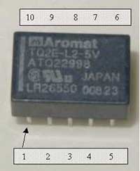
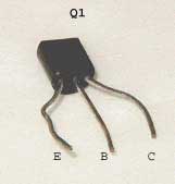
UPDATE:
Here is the pinout for the Relay and for the Transistor
|
|
|
 |
|
|
|
|
One of the things we're going to have to take care of here is the calibration of the circuit. What I mean by this is that you will have to set VR1 to your 'trigger temperature'. I've elected to set mine at 60C (140F). Don't ask me why…it just seems like a good temperature.
So I need a 60C source. Easiest way to do this is to heat up a cup of water to 60C and then stick the Thermister in the cup. Now, we need to start this calibration in a non-alarm state which means the Green LED should be lit.
NOTE: VR1 will vary in direction that it will need to be turned depending on how you hook it up. Depending on which two of the three pins you use, turning the screw clockwise will increase resistance OR decrease resistance. The way I have set mine up and the way the instructions work is if VR1 is setup to increase resistance as the screw is turned clockwise. If you happen to hook it up the other way, it's really no big deal. It just means that when I say turn it clockwise, you will have to turn it counter-clockwise.
- Turn VR1 to completely CC (Counter Clockwise). For the type of Potentiometer I used, it will make a slight clicking noise when it has reached a limit…otherwise, it keeps turning.
- Slowly increase VR1 just to the point that the circuit fires and the relay latches. You can see this happen by watching when the Red LED turns On….remember, Red == Bad. Remember to do turn VR1 very slowly when you are close to the trip point.
- If you happen to trip the relay and want to go back and try again, turn VR1 all the way CC again AND then hit the reset switch. The Green LED should light up once again. The goal here is to turn VR1 BARELY enough to cause the Red LED to light.
- Once you've gotten this to behave correctly, the circuit is calibrated for a 60C trip point.
|
|
|
|
Now, after you've tested and verified that the circuit is working properly, we'll proceed with the installation. Basically, this section will show you 'what and how' to connect to the terminal blocks. Remember, one of the two pin terminal blocks will be used for the power wires, and the other two pin block will be used for passing the Power-On signal between the motherboard and the PSU.
The installation location will depend on where you would like the PCB to reside. It's possible to cram this thing into the PSU itself, or if you're not so daring, you can simply mount it somewhere inside the case out of the way.
For simplicity, we'll take the external route. This will involve tapping into the 'Standby' power and cutting the 'Power-On' wired and inserting the PCB in series with it.
This is what your ATX connector on the motherboard should look like as far as color coding is concerned.
|
|
|
|
|
The one and only Green wire that you should see is the 'Power-On' signal that we are concerned with.
The other wires we will be using is single Purple wire you should see. To go along with the purple wire, we will need a ground. Any of the Black wires will suffice for this.
|
|
|
|
|
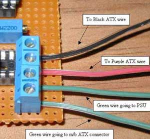
Here's what you need to do
- Get out a pair of wire cutters and find a good location to cut the wire.
- Strip a small piece of insulation off of both ends of the now cut Green wire
- Insert the now stripped ends of wire into the terminal block on the circuit board and secure it. There is no polarity to worry about here. Just take your pick of each end.
- Next, use something like a wire tap-in on Purple and Black wires. Here's what the tap-ins look like if you're not familiar.
|
|
In this picture, the Red wire is taped into the black wire.
For clarity though, I'd recommend using a black wire to tap into the Ground wire and a Red wire to tap into the Purple wire. The Red wire will be the circuit's +5V power source.
|
|
|
|
|
|
Wire Tap-In
|
|
 |
|
|
- Now, Insert the Black and Red wires coming from the tap-ins into the two pin block on the circuit board. Make sure that you have the polarity correct! Check the schematic to make sure of where the ground and +5V connections are.
|
|
|
|
|
|
Things should look a little like this now.
|
|
|
 |
|
|
|
Parts List:
|
|
|
|
|
|
|
I attempted to use commonly available parts as much as possible. Pretty much every part used here is/should be available as RadioCrack with the exception of the relay. I did quite a bit of looking around for the relay and found a place in Garland, TX that sells a model that meets the requirements for this project. Best part is, you can get the relay from them for only a buck! Take THAT 10-10-220 ! This place is what's called a surplus electronics company. They get overstock and surplus items from various sources and resell them…so, the part was quite a bit cheaper because of this. Normally you'll pay anywhere from $4-8 for this type of relay at retail locations.
Special note: If you decide to use different LEDs than those listed below, the current limiting resistor value will need to be recalculated. If you need to know the new value, just follow this equation. The information you need for the equation should be found on the package the LED comes in.
5V – (LED operating Voltage) / (LED operating current in Amps)
This will give you a value in ohms.
Here's an example. No charge for this one:
LED chosen has an operating voltage of 2.6V and a peak current of 30mA. (30mA is ..030 Amps for the mathematically challenged)
|
|
|
|
This would yield (5V – 2.6V) / .030 = 80ohms
|
|
|
|
|
Since we calculated this using the peak LED current, you DON'T want to use a resistor with a smaller value than 80ohms. Higher is OK, but the brightness of the LED will go down progressively.
|
|
|
Here's the List:
Resistors R/S Part #
1 – 1M ohm 271-1356
3 – 10K ohm 271-1335
1- 150 ohm 271-1312
1 – 10K Pot. 271-343
Diodes
2 – 1N914 276-1620
LEDs
1 – Green 276-304
1 – Red 276-308
Transistor
1 – MPS2222A 276-2009
IC
1 – LM339N 276-1712
Thermister
1 – NTC 10K (@25C) Used one from my DD5 kit. You'll have to find your own.
Relay
1 – Dual Coil Latching REL1038 (Available at Bgmicro.com for $1/ea.)
Misc.
2 – Terminal block Catalog shows this as special order item but was available in the store near me
2 – 14pin DIP sockets 276-1999
1 – Momentary switch Take your pick. MUST BE A MOMENTARY TYPE SWITCH
Your choice of board material for building the circuit onto.
2 – Wire Tap-in 64-3052
|
|
|
|
| Random Forum Pic |
 |
| From Thread: Another #Rotor style block... |
|
| | ProCooling Poll: |
| So why the hell not? |
|
I agree!
|
 67% 67%
|
|
What?
|
 17% 17%
|
|
Hell NO!
|
 0% 0%
|
|
Worst Poll Ever.
|
 17% 17%
|
Total Votes:18Please Login to Vote!
|
|